SEAT BELT SEAT BELT WARNING SYSTEM TERMINALS OF ECU
CHECK COMBINATION METER ASSEMBLY (for Optitron Meter Type)

Disconnect the E17 combination meter assembly connector.
Measure the voltage and resistance according to the value(s) in the table below.
- HINT:
-
Measure the values on the wire harness side with the connector disconnected.
| Terminal No. (Symbol) | Terminal Description | Condition | Specified Condition |
|---|---|---|---|
| E17-40 (B) - Body ground | Auxiliary battery power supply | Ignition switch off*1
Always*2 |
11 to 14 V |
| E17-39 (IG+) - Body ground | Ignition power supply | Ignition switch off | Below 1 V |
| Ignition switch ON | 11 to 14 V | ||
| E17-21 (ES) - Body ground | Ground | Always | Below 1 Ω |
| E17-2 (EP) - Body ground | Ground | Always | Below 1 Ω |
| E17-8 (BKL) - Body ground | Driver seat belt buckle switch signal | Driver seat belt fastened | 10 kΩ or higher |
| Driver seat belt unfastened | Below 1 Ω |
*1: for HV Model
*2: for Gasoline Model
CHECK COMBINATION METER ASSEMBLY (for TFT Meter Type)
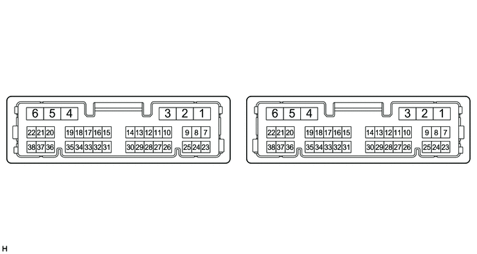
Disconnect the E143 combination meter assembly connectors.
Measure the resistance and voltage according to the value(s) in the table below.
- HINT:
-
Measure the values on the wire harness side with the connector disconnected.
| Terminal No. (Symbol) | Terminal Description | Condition | Specified Condition |
|---|---|---|---|
| E143-5 (B) - Body ground | Auxiliary battery power supply | Ignition switch off | 11 to 14 V |
| E143-6 (IG+) - Body ground | Ignition power supply (IG signal) | Ignition switch ON → off | 11 to 14 V → Below 1 V |
| E143-2 (ES) - Body ground | Ground | Always | Below 1 Ω |
| E143-29 (BKL) - Body ground | Driver seat belt buckle switch signal | Driver seat belt fastened | 10 kΩ or higher |
| Driver seat belt unfastened | Below 1 Ω |
CHECK POWER DISTRIBUTION BOX ASSEMBLY AND MAIN BODY ECU (MULTIPLEX NETWORK BODY ECU)
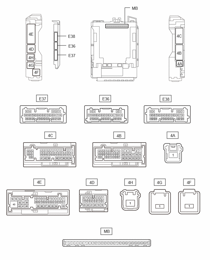
Remove the main body ECU (multiplex network body ECU) from the power distribution box assembly.
Measure the voltage and resistance according to the value(s) in the table below.
| Terminal No. (Symbol) | Terminal Description | Condition | Specified Condition |
|---|---|---|---|
| MB-13 (GND1) - Body ground | Ground | Always | Below 1 Ω |
| MB-14 (GND2) - Body ground | Ground | Always | Below 1 Ω |
| MB-26 (BECU) - Body ground | Auxiliary battery power supply | Ignition switch off*1
Always*2 |
11 to 14 V |
| MB-27 (IGR) - Body ground | IG power supply | Ignition switch ON | 11 to 14 V |
| Ignition switch off | Below 1 V |
*1: for HV Model
*2: for Gasoline Model
Reconnect the power distribution box assembly connectors.
Measure the voltage according to the value(s) in the table below.
| Terminal No. (Symbol) | Terminal Description | Condition | Specified Condition |
|---|---|---|---|
| 4E-4 - Body ground | Rear center seat belt buckle switch signal | Rear center seat belt fastened | 11 to 14 V |
| Rear center seat belt unfastened | Below 1 V | ||
| 4E-8 - Body ground | Rear RH seat belt buckle switch signal | Rear RH seat belt fastened | 11 to 14 V |
| Rear RH seat belt unfastened | Below 1 V | ||
| 4E-11 - Body ground | Front passenger seat belt buckle switch signal | Front passenger seat belt fastened | 11 to 14 V |
| Front passenger seat belt unfastened | Below 1 V | ||
| 4E-19 - Body ground | Rear LH seat belt buckle switch signal | Rear LH seat belt fastened | 11 to 14 V |
| Rear LH seat belt unfastened | Below 1 V | ||
| 4E-29 - Body ground | Occupant detection sensor signal | Ignition switch ON, front passenger seat occupied | Below 1 V |
| Ignition switch ON, front passenger seat not occupied | 11 to 14 V | ||
| 4E-1 - Body ground | Rear door courtesy light switch RH input | Rear door RH closed (OFF) | 4.7 to 5.3 V |
| Rear door RH open (ON) | Below 1 V | ||
| 4E-26 - Body ground | Rear door courtesy light switch LH input | Rear door LH closed (OFF) | 4.7 to 5.3 V |
| Rear door LH open (ON) | Below 1 V |