METER / GAUGE / DISPLAY METER / GAUGE SYSTEM(for Optitron Meter Type) Engine Oil Level Sensor Circuit
DESCRIPTION
The combination meter assembly and engine oil level sensor are connected via direct line. The combination meter assembly determines the engine oil level based on the engine oil level sensor status signal.
- HINT:
-
The coolant temperature signal and engine speed signal is sent from the ECM to the combination meter assembly via CAN communication. Because an accurate engine oil level cannot be detected when the engine is cold or operating at high speeds, warning control is only performed after the engine is warmed up and the engine is stopped or idling.
WIRING DIAGRAM
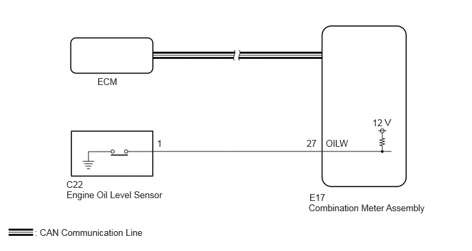
CAUTION / NOTICE / HINT
- NOTICE:
- ·
When replacing the combination meter assembly, always replace it with a new one. If a combination meter assembly which was installed to another vehicle is used, the information stored in it will not match the information from the vehicle and a DTC may be stored.
·When replacing the combination meter assembly, update the ECU security key.
·The following troubleshooting procedure is based on the assumption that the SFI system is normal. Confirm that the SFI system is not malfunctioning before performing the following procedure.
·Check the engine oil level, before performing the following procedure.
PROCEDURE
Read the Data List according to the display on the GTS.
- Body Electrical > Combination Meter > Data List
-
Tester Display Measurement Item Range Normal Condition Diagnostic Note Oil Level Switch Engine oil level sensor input OFF or ON OFF: Engine oil level not low
ON: Engine oil level low-
- Body Electrical > Combination Meter > Data List
-
Tester Display Oil Level Switch - 50003 409 45
- Result:
Result Proceed to The Data List item changes correctly A The Data List item do not change correctly B
A
B
- Result:
Proceed to OK NG
OK
NG
Disconnect the E17 combination meter assembly connector.
Measure the resistance according to the value(s) in the table below.
- Standard Resistance:
Tester Connection Condition Specified Condition Click Location & Routing(C22,E17)Location & Routingewd_type=routing;type=c,c;code=C22,E17
Click Connector(C22)Engine Compartment>Engine Wire>Engine Oil Level Sensorewd_type=component;type=c;code=C22;pinno=1
Click Connector(E17)Instrument Panel>Instrument Panel Wire / Radio Wiring Sub-Assy / Telephone Computer Wire>Combination Meter Assemblyewd_type=component;type=c;code=E17;pinno=27
C22-1 - E17-27 (OILW) Always Below 1 Ω C22-1 or E17-27 (OILW) - Body ground Always 10 kΩ or higher
- Result:
Proceed to OK NG
OK
NG