STOP AND START STOP AND START SYSTEM P253014 Ignition Switch Circuit Short to Ground or Open
DESCRIPTION
If the engine stop and start ECU receives the OFF signal from the certification ECU (smart key ECU assembly) when communication with the ECM is normal, the engine stop and start ECU will output DTC P253014.
| DTC No. | Detection Item | DTC Detection Condition | Trouble Area | Warning Indicate | Note |
|---|---|---|---|---|---|
| P253014 | Ignition Switch Circuit Short to Ground or Open | All of the following conditions are met for 10 seconds or more (1 trip detection logic):
·
Ignition switch off signal is input. ·
Communication with the ECM is normal. ·
Ignition switch (communication) to ON. |
·
Wire harness or connector ·
EFI-MAIN NO. 1 relay ·
IGP relay ·
Certification ECU (Smart key ECU assembly) ·
Engine stop and start ECU |
Does not come on | SAE Code: P2531 |
CONFIRMATION DRIVING PATTERN
CONFIRMATION AFTER TROUBLESHOOTING
- HINT:
- ·
If the cable is disconnected from the battery terminal, stop and start control is prohibited until refresh charge is completed.
In this case, let the vehicle idle to complete the refresh charge. The refresh charge is complete when the Data List item "Status of Battery Charge Control" changes from "Refresh Charge Mode". (Usually, idling the engine for 5 to 60 minutes with the battery fluid temperature at 11°C (52°F) or higher, the refresh charge will be completed.)
·If the GTS is not available and the Data List item "Status of Battery Charge Control" cannot be checked, charge the battery by idling the engine for approximately 5 to 60 minutes or driving the vehicle, and then drive the vehicle and check that stop and start control operates.
If the engine is started with the hood open, the system determines that a jump start has occurred. Therefore, make sure that the hood is closed before starting the engine and driving the vehicle.
·After the refresh charge completes, turn the ignition switch off, wait for at least 30 seconds, and then start the engine again. If the vehicle enters refresh charge mode again while the engine is idling, the initial refresh charge did not properly complete, so wait for the refresh charge to complete.
·Allow the engine to idle for 3 minutes after it is warmed up and check that the engine idle speed is within 50 rpm of the target idle speed.
Clear the DTCs.
- Powertrain > Stop and Start > Clear DTCs
- 50002 392
Start the engine and warm it up.
Drive the vehicle at 7 km/h (4.3 mph) or more.
- CAUTION:
-
When performing Confirmation Driving Pattern, obey all speed limits and traffic laws.
Depress the brake pedal and stop the vehicle.
Keep the engine stopped by stop and start control for 10 second or more. (Keep the shift lever in D.)
Release the brake pedal with the shift lever in D to start the engine.
Check that DTCs are not output.
- Powertrain > Stop and Start > Trouble Codes
- 50001 392
STOP AND START SYSTEM OPERATION CHECK
WIRING DIAGRAM
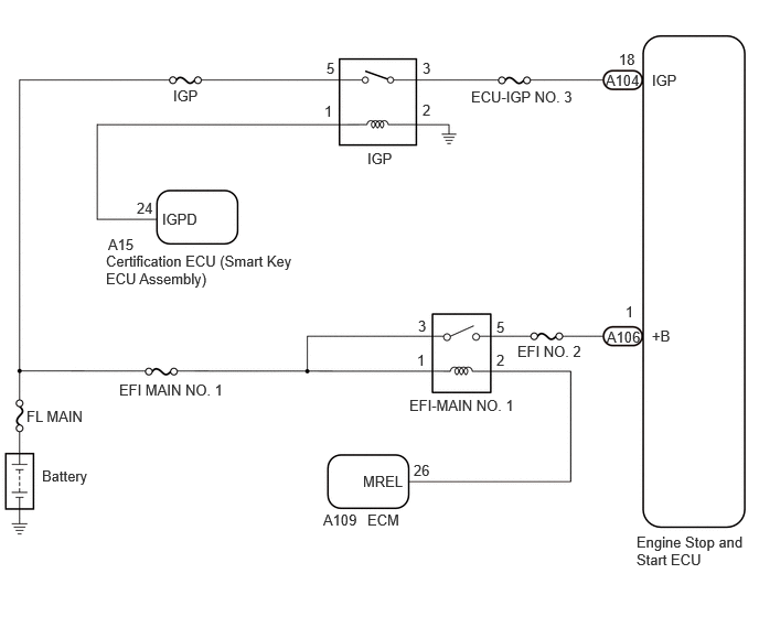
CAUTION / NOTICE / HINT
- NOTICE:
- ·
Before replacing the engine stop and start ECU, read the number of starter operations and write it into a new engine stop and start ECU.
·After replacing the engine stop and start ECU or air conditioning amplifier assembly, reset and perform learning of the air conditioning information in the engine stop and start ECU.
·After replacing the engine stop and start ECU, perform learning of the external backup boost converter (eco run vehicle converter assembly).
·Inspect the fuses for circuits related to this system before performing the following procedure.
- HINT:
- ·
Using the GTS, read the Freeze Frame Data before troubleshooting. System condition information is recorded as Freeze Frame Data the moment a DTC is stored. This information can be useful when troubleshooting.
·DTCs for the stop and start system are not cleared even if the malfunction has been repaired. After repairing the malfunction, be sure to clear the DTCs.
PROCEDURE
According to the display on the GTS, read the Data List.
- Powertrain > Stop and Start > Data List
-
Tester Display IG Switch - 50003 392 203
- Result:
Tester Display Result Proceed to IG Switch ON A OFF B
A
B
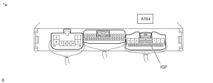
| *a | Component with harness connected
(Engine Stop and Start ECU) |
- | - |
Turn the ignition switch to ON.
Measure the voltage according to the value(s) in the table below.
- Standard Voltage:
Tester Connection Switch Condition Specified Condition Click Location & Routing(A104)Location & Routingewd_type=routing;type=c;code=A104
Click Connector(A104)Instrument Panel>Engine Room Main Wire>Engine Stop and Start ECUewd_type=component;type=c;code=A104;pinno=18
A104-18 (IGP) - Body ground Ignition switch ON 9.5 to 14 V
- Result:
Proceed to OK NG
OK
NG

| *a | Component with harness connected
(Engine Stop and Start ECU) |
- | - |
Turn the ignition switch to ON.
Measure the voltage according to the value(s) in the table below.
- Standard Voltage:
Tester Connection Condition Specified Condition Click Location & Routing(A106)Location & Routingewd_type=routing;type=c;code=A106
Click Connector(A106)Instrument Panel>Engine Room Main Wire>Engine Stop and Start ECUewd_type=component;type=c;code=A106;pinno=1
A106-1 (+B) - Body ground Ignition switch ON 9.5 to 14 V
- Result:
Proceed to OK NG
OK
NG
Disconnect the engine stop and start ECU connector.
Remove the EFI-MAIN NO. 1 relay from the No. 1 engine room relay block and No. 1 junction block assembly.
Measure the resistance according to the value(s) in the table below.
- Standard Resistance:
Tester Connection Condition Specified Condition Click Location & Routing(A106)Location & Routingewd_type=routing;type=c;code=A106
Click Connector(A106)Instrument Panel>Engine Room Main Wire>Engine Stop and Start ECUewd_type=component;type=c;code=A106;pinno=1
A106-1 (+B) - 5 (EFI-MAIN NO. 1 relay holder) Always Below 1 Ω A106-1 (+B) - Body ground and other terminals Always 10 kΩ or higher 5 (EFI-MAIN NO. 1 relay holder) - Body ground and other terminals Always 10 kΩ or higher
- Result:
Proceed to OK NG
OK
NG
Disconnect the engine stop and start ECU connector.
Remove the IGP relay from the No. 1 engine room relay block and No. 1 junction block assembly
Measure the resistance according to the value(s) in the table below.
- Standard Resistance:
Tester Connection Condition Specified Condition Click Location & Routing(A104)Location & Routingewd_type=routing;type=c;code=A104
Click Connector(A104)Instrument Panel>Engine Room Main Wire>Engine Stop and Start ECUewd_type=component;type=c;code=A104;pinno=18
A104-18 (IGP) - 3 (IGP relay holder) Always Below 1 Ω A104-18 (IGP) - Body ground and other terminals Always 10 kΩ or higher 3 (IGP relay holder) - Body ground and other terminals Always 10 kΩ or higher
- Result:
Proceed to OK NG
OK
NG