RM38N0EC _56 Audio / Visual / Telematics _111822 AUDIO / VIDEO _0502892 AUDIO AND VISUAL SYSTEM J

AUDIO / VIDEO  AUDIO AND VISUAL SYSTEM  Sound cannot be Heard Sound Quality is Poor only when Replaying USB Storage Device  


WIRING DIAGRAM
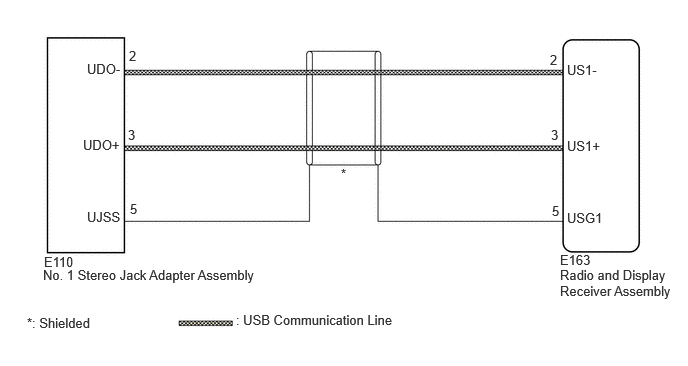
E429903E23
1.344,0.5 1.521,0.677 0.177,0.177 10 false 2 0.865,1.427 1.313,1.625 0.448,0.198 10 false UDO+ 0.906,2.177 1.313,2.365 0.406,0.188 10 false UJSS 5.906,2.188 6.313,2.365 0.406,0.177 10 false USG1 5.906,1.438 6.344,1.615 0.438,0.177 10 false US1+ 5.906,0.646 6.281,0.854 0.375,0.208 10 false US1- 0.458,2.646 0.896,2.844 0.438,0.198 10 false E110 0.448,2.781 2.75,3 2.302,0.219 10 false No. 1 Stereo Jack Adapter Assembly 2.458,3.25 4.135,3.438 1.677,0.188 10 false : USB Communication Line 3.552,1.729 3.719,1.896 0.167,0.167 10 false * 5.833,2.625 6.25,2.813 0.417,0.188 10 false E163 5.833,2.781 7.052,3.167 1.219,0.385 10 false Radio and Display Receiver Assembly 5.729,0.542 5.906,0.719 0.177,0.177 10 false 2 1.333,1.323 1.51,1.5 0.177,0.177 10 false 3 1.354,2.094 1.531,2.271 0.177,0.177 10 false 5 5.75,2.115 5.927,2.292 0.177,0.177 10 false 5 5.74,1.323 5.917,1.5 0.177,0.177 10 false 3 0.906,0.635 1.302,0.854 0.396,0.219 10 false UDO- 0.281,3.281 1.125,3.51 0.844,0.229 10 false *: Shielded

CAUTION / NOTICE / HINT

NOTICE:

Depending on the parts that are replaced during vehicle inspection or maintenance, performing initialization, registration or calibration may be needed.

Click hereAudio / Visual / Telematics>AUDIO / VIDEO>AUDIO AND VISUAL SYSTEM>PRECAUTION


PROCEDURE

1.CHECK HARNESS AND CONNECTOR (RADIO AND DISPLAY RECEIVER ASSEMBLY - NO. 1 STEREO JACK ADAPTER ASSEMBLY)
a.

Disconnect the E163 radio and display receiver assembly connector.


b.

Disconnect the E110 No. 1 stereo jack adapter assembly connector.
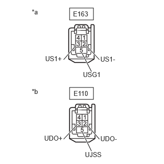

c.
E433937C24
1.458,0.167 1.958,0.417 0.5,0.25 1.458,1.833 1.958,2.083 0.5,0.25 1.333,1.25 1.604,0.938 true 2.083,1.25 1.792,0.938 true 1.917,1.5 1.708,1.094 true 1.333,2.917 1.625,2.604 true 2.083,2.917 1.813,2.604 true 1.917,3.167 1.719,2.76 true 0.667,0.167 0.917,0.333 0.25,0.167 10 false *a 0.667,1.833 0.917,2 0.25,0.167 10 false *b 1.531,0.208 1.938,0.365 0.406,0.156 10 false E163 1.542,1.875 1.958,2.083 0.417,0.208 10 false E110 0.948,1.146 1.333,1.323 0.385,0.177 10 false US1+ 2.104,1.156 2.479,1.333 0.375,0.177 10 false US1- 1.74,1.479 2.219,1.646 0.479,0.167 10 false USG1 0.927,2.813 1.333,2.979 0.406,0.167 10 false UDO+ 2.104,2.823 2.5,3 0.396,0.177 10 false UDO- 1.781,3.156 2.177,3.323 0.396,0.167 10 false UJSS
*a Front view of wire harness connector
(to Radio and Display Receiver Assembly)
*b Front view of wire harness connector
(to No. 1 Stereo Jack Adapter Assembly)


Measure the resistance according to the value(s) in the table below.

Standard Resistance:
Tester Connection Condition Specified Condition

Click Location & Routing(E163,E110)Location & Routing

Click Connector(E163)Instrument Panel>Instrument Panel Wire / Telephone Computer Wire>Navigation Receiver Assembly

Click Connector(E110)Instrument Panel>Instrument Panel Wire / Telephone Computer Wire>No. 1 Stereo Jack Adapter Assembly

E163-2 (US1-) - E110-2 (UDO-) Always Below 1 Ω
E163-3 (US1+) - E110-3 (UDO+) Always Below 1 Ω
E163-5 (USG1) - E110-5 (UJSS) Always Below 1 Ω
E163-2 (US1-) or E110-2 (UDO-) - Body ground Always 10 kΩ or higher
E163-3 (US1+) or E110-3 (UDO+) - Body ground Always 10 kΩ or higher
E163-5 (USG1) or E110-5 (UJSS) - Body ground Always 10 kΩ or higher


Result:
Proceed to
OK
NG


OK

2.CHECK NO. 1 STEREO JACK ADAPTER ASSEMBLY

NG

REPAIR OR REPLACE HARNESS OR CONNECTOR

2.CHECK NO. 1 STEREO JACK ADAPTER ASSEMBLY
a.

Replace the No. 1 stereo jack adapter assembly with a new or known good one.

Click hereAudio / Visual / Telematics>AUDIO / VIDEO>STEREO JACK ADAPTER ASSEMBLY>REMOVAL


b.

Check if the problem symptom recurs.


Result:
Result Proceed to
Malfunction disappears A
Malfunction occurs B


A

END (NO. 1 STEREO JACK ADAPTER ASSEMBLY MALFUNCTION)

B