AUDIO / VIDEO AUDIO AND VISUAL SYSTEM USB Audio System Recognition/Play Error
WIRING DIAGRAM
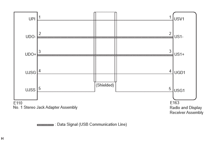
CAUTION / NOTICE / HINT
- NOTICE:
-
Depending on the parts that are replaced during vehicle inspection or maintenance, performing initialization, registration or calibration may be needed.
- HINT:
- ·
When many folders or files exist in the USB storage device, it may take a while to begin playback.
·When using a USB storage device, files that are protected by copyright or encrypted cannot be played
·If a USB hub is being used, remove it.
·When files on the USB storage device are not played in the sorted order, perform the following procedure.
(a)Assign a number to the start of each file name.
(b)Move the files to a folder and copy each folder to the USB storage device.
PROCEDURE
Disconnect the USB storage device from the No.1 stereo jack adapter assembly.
Check that playable files exist in the USB storage device.
Check that the USB storage device being used by the customer is a compatible version and format.
- Result:
Result Proceed to The format of the USB storage device is compatible A Playable files do not exist
The format of the USB storage device is not compatibleB
A
B
Disconnect the E163 radio and display receiver assembly connector.
Disconnect the E110 No. 1 stereo jack adapter assembly connector.
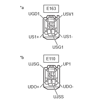
| *a | Front view of wire harness connector
(to Radio and Display Receiver Assembly) |
| *b | Front view of wire harness connector
(to No. 1 Stereo Jack Adapter Assembly) |
Measure the resistance according to the value(s) in the table below.
- Standard Resistance:
Tester Connection Condition Specified Condition Click Location & Routing(E163,E110)Location & Routingewd_type=routing;type=c,c;code=E163,E110
Click Connector(E163)Instrument Panel>Instrument Panel Wire / Telephone Computer Wire>Navigation Receiver Assemblyewd_type=component;type=c;code=E163;pinno=1,2,3,4,5
Click Connector(E110)Instrument Panel>Instrument Panel Wire / Telephone Computer Wire>No. 1 Stereo Jack Adapter Assemblyewd_type=component;type=c;code=E110;pinno=1,2,3,4,5
E163-1 (USV1) - E110-1 (UPI) Always Below 1 Ω E163-2 (US1-) - E110-2 (UDO-) Always Below 1 Ω E163-3 (US1+) - E110-3 (UDO+) Always Below 1 Ω E163-4 (UGD1) - E110-4 (UJSG) Always Below 1 Ω E163-5 (USG1) - E110-5 (UJSS) Always Below 1 Ω E163-1 (USV1) or E110-1 (UPI) - Body ground Always 10 kΩ or higher E163-2 (US1-) or E110-2 (UDO-) - Body ground Always 10 kΩ or higher E163-3 (US1+) or E110-3 (UDO+) - Body ground Always 10 kΩ or higher E163-4 (UGD1) or E110-4 (UJSG) - Body ground Always 10 kΩ or higher E163-5 (USG1) or E110-5 (UJSS) - Body ground Always 10 kΩ or higher
- Result:
Proceed to OK NG
OK
NG
Disconnect the E110 No. 1 stereo jack adapter assembly connector.
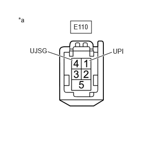
| *a | Front view of wire harness connector
(to No. 1 Stereo Jack Adapter Assembly) |
Measure the voltage according to the value(s) in the table below.
- Standard Voltage:
Tester Connection Condition Specified Condition Click Location & Routing(E110)Location & Routingewd_type=routing;type=c;code=E110
Click Connector(E110)Instrument Panel>Instrument Panel Wire / Telephone Computer Wire>No. 1 Stereo Jack Adapter Assemblyewd_type=component;type=c;code=E110;pinno=1,4
E110-1 (UPI) - E110-4 (UJSG) Ignition switch ON 4.5 to 5.5 V
- HINT:
-
Measure the voltage with the radio and display receiver assembly connectors connected.
- Result:
Proceed to OK NG
OK
NG
Format the USB storage device to delete the audio files.
- NOTICE:
-
When formatting the USB storage device, all audio files stored in the device will be deleted. Make sure to back up the audio files before performing this procedure.
Restore the data and check if the problem can be reproduced.
- Result:
Result Proceed to Malfunction disappears A Malfunction occurs. B
A
B
Disconnect the USB storage device from the No. 1 stereo jack adapter assembly.
Turn the ignition switch from off to ON
- HINT:
-
If another USB storage device is to be connected, it is necessary to turn the ignition switch off in order for the device to be detected.
Connect a known good USB storage device to the No. 1 stereo jack adapter assembly.
- HINT:
-
When a USB storage device is used, replace it with another device and perform the inspection.
Perform the operation again and check if the problem symptom recurs.
- Result:
Result Proceed to Malfunction disappears A Malfunction occurs B
A
B
Replace the No. 1 stereo jack adapter assembly with a new or known good one.
Check if the problem symptom recurs.
- Result:
Result Proceed to Malfunction disappears A Malfunction occurs B
A
B