HEATING / AIR CONDITIONING CONDENSER INSTALLATION
PROCEDURE

 884A0
1.INSTALL COOLER CONDENSER ASSEMBLY
884A0
1.INSTALL COOLER CONDENSER ASSEMBLY
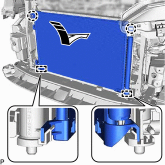

|
Install in this Direction |
Engage the 2 guides and 2 claws to install the cooler condenser assembly as shown in the illustration.
- NOTICE:
-
Do not damage the cooler condenser assembly and radiator assembly when removing the cooler condenser assembly.
- HINT:
-
If a new cooler condenser assembly is installed, add compressor oil to the cooler condenser assembly as follows.
- Capacity:
Add 40 cc (1.35 fl. oz)
- for HV Model:
Compressor Oil (ND-OIL 11 or equivalent)
- for Gasoline Model:
Compressor Oil (ND-OIL 8 or equivalent)
88710E
2.CONNECT AIR CONDITIONING TUBE AND ACCESSORY ASSEMBLY
Remove the vinyl tape from the air conditioning tube and accessory assembly and cooler condenser assembly.
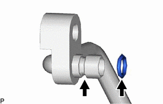
Sufficiently apply compressor oil to a new O-ring and the fitting surface of the air conditioning tube and accessory assembly.
- for HV Model:
Compressor Oil (ND-OIL 11 or equivalent)
- for Gasoline Model:
Compressor Oil (ND-OIL 8 or equivalent)
Install the O-ring to the air conditioning tube and accessory assembly.
- NOTICE:
-
Keep the O-ring and O-ring fitting surface free from foreign matter.
Connect the No. 1 cooler refrigerant discharge hose to the cooler condenser assembly with the bolt.
- Torque:
- 9.8 N*m (100 kgf*cm, 87 in.*lbf)
88711
3.CONNECT NO. 1 COOLER REFRIGERANT DISCHARGE HOSE
Remove the vinyl tape from the No. 1 cooler refrigerant discharge hose and cooler condenser assembly.
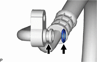
Sufficiently apply compressor oil to a new O-ring and the fitting surface of the No. 1 cooler refrigerant discharge hose.
- for HV Model:
Compressor Oil (ND-OIL 11 or equivalent)
- for Gasoline Model:
Compressor Oil (ND-OIL 8 or equivalent)
Install the O-ring to the No. 1 cooler refrigerant discharge hose.
- NOTICE:
-
Keep the O-ring and O-ring fitting surface free from foreign matter.
Connect the No. 1 cooler refrigerant discharge hose to the cooler condenser assembly with the bolt.
- Torque:
- 5.4 N*m (55 kgf*cm, 48 in.*lbf)
53205
4.INSTALL UPPER RADIATOR SUPPORT SUB-ASSEMBLY
for M20C-FKS, M20D-FKS:
for A25D-FXS, A25F-FXS:
53630
5.CONNECT HOOD LOCK CONTROL CABLE ASSEMBLY
for M20C-FKS, M20D-FKS:
for A25D-FXS, A25F-FXS:
53510
6.INSTALL HOOD LOCK ASSEMBLY
16595B
7.INSTALL NO. 1 RADIATOR AIR GUIDE LH
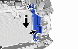
|
|
Install in this Direction |
Engage the guide and claw as shown in the illustration.
Install the No. 1 radiator air guide LH with the clip.
Engage the clamp.
16593B
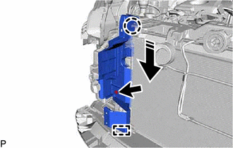
8.INSTALL NO. 1 RADIATOR AIR GUIDE RH
|
|
Install in this Direction |
Engage the guide and claw as shown in the illustration.
Install the No. 1 radiator air guide RH with the clip.
16695A
9.INSTALL FRONT RADIATOR SIDE AIR GUIDE PLATE LH
Engage the 2 claws to install the front radiator side air guide plate LH.
16691A
10.INSTALL FRONT RADIATOR SIDE AIR GUIDE PLATE RH
Engage the 2 claws to install the front radiator side air guide plate RH.
16563D
11.INSTALL NO. 3 RADIATOR TO SUPPORT SEAL
Engage the 2 claws to install the No. 3 radiator to support seal.
16562M
12.INSTALL NO. 2 RADIATOR TO SUPPORT SEAL
Engage the 2 claws to install the No. 2 radiator to support seal.
52021
13.INSTALL FRONT BUMPER REINFORCEMENT SUB-ASSEMBLY
52614
14.INSTALL NO. 2 FRONT BUMPER ENERGY ABSORBER
16681A
15.INSTALL UPPER RADIATOR AIR GUIDE PLATE
for M20C-FKS, M20D-FKS:
for A25D-FXS, A25F-FXS:
17750A
16.INSTALL INLET AIR CLEANER ASSEMBLY
for M20C-FKS, M20D-FKS:
for A25D-FXS, A25F-FXS:
17.INSTALL FRONT BUMPER ASSEMBLY
for SFTM Made:
for GTMC Made:
18.CHARGE AIR CONDITIONING SYSTEM WITH REFRIGERANT
19.WARM UP COMPRESSOR (for HV Model)
20.WARM UP ENGINE (for Gasoline Model)
21.INSPECT FOR REFRIGERANT LEAK
53301
22.ADJUST HOOD SUB-ASSEMBLY