LIGHTING (EXT) LIGHTING SYSTEM Door Mirror Foot Light Circuit
DESCRIPTION
The main body ECU (multiplex network body ECU) controls the door mirror foot lights.
WIRING DIAGRAM
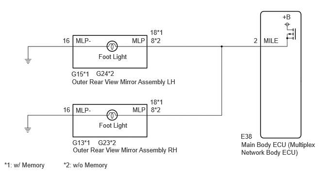
CAUTION / NOTICE / HINT
- NOTICE:
-
If the main body ECU (multiplex network body ECU) is replaced, refer to Service Bulletin.
PROCEDURE
Perform the Active Test according to the display on the GTS.
- Body Electrical > Main Body > Active Test
-
Tester Display Measurement Item Control Range Diagnostic Note Exterior Illumination Door mirror foot lights OFF or ON -
- Body Electrical > Main Body > Active Test
-
Tester Display Exterior Illumination - 50004 449 25
- OK:
Door mirror foot lights illuminate.
- Result:
Result Proceed to OK A NG (Left side door mirror foot light does not illuminate) B NG (Right side door mirror foot light does not illuminate) C NG (Both left and right door mirror foot lights do not illuminate) D
A
B
C
D
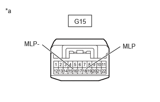
| *a | Component without harness connected
(Outer Rear View Mirror Assembly LH) |
Remove the outer rear view mirror assembly LH. ( w/ Memory)
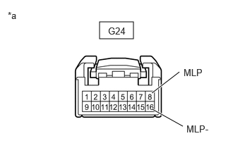
| *a | Component without harness connected
(Outer Rear View Mirror Assembly LH) |
Remove the outer rear view mirror assembly LH. ( w/o Memory)
Apply auxiliary battery voltage to the door mirror foot light and check that the light illuminates.
- OK:
w/ Memory Measurement Condition Specified Condition Auxiliary battery positive (+) → Terminal 18 (MLP)
Auxiliary battery negative (-) → Terminal 16 (MLP-)Door mirror foot light illuminates
w/o Memory Measurement Condition Specified Condition Auxiliary battery positive (+) → Terminal 8 (MLP)
Auxiliary battery negative (-) → Terminal 16 (MLP-)Door mirror foot light illuminates
- Result:
Proceed to OK NG
OK
NG
Disconnect the E38 main body ECU (multiplex network body ECU) connector.
Measure the resistance according to the value(s) in the table below.
- Standard Resistance:
w/ Memory Tester Connection Condition Specified Condition Click Location & Routing(G15,E38)Location & Routingewd_type=routing;type=c,c;code=G15,E38
Click Connector(G15)Body>Front Door Wire RH / Front Door Wire LH>Outer Rear View Mirror Assembly LHewd_type=component;type=c;code=G15;pinno=18,16
Click Connector(E38)Instrument Panel>Instrument Panel Wire / Radio Wiring Sub-Assy / Telephone Computer Wire>Multiplex Network Body ECUewd_type=component;type=c;code=E38;pinno=2
G15-18 (MLP) - E38-2 (MILE) Always Below 1 Ω G15-16 (MLP-) - Body ground Always Below 1 Ω
w/o Memory Tester Connection Condition Specified Condition Click Location & Routing(G24,E38)Location & Routingewd_type=routing;type=c,c;code=G24,E38
Click Connector(G24)Body>Front Door Wire RH / Front Door Wire LH>Outer Rear View Mirror Assembly LHewd_type=component;type=c;code=G24;pinno=8,16
Click Connector(E38)Instrument Panel>Instrument Panel Wire / Radio Wiring Sub-Assy / Telephone Computer Wire>Multiplex Network Body ECUewd_type=component;type=c;code=E38;pinno=2
G24-8 (MLP) - E38-2 (MILE) Always Below 1 Ω G24-16 (MLP-) - Body ground Always Below 1 Ω
- Result:
Proceed to OK NG
OK
NG
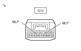
| *a | Component without harness connected
(Outer Rear View Mirror Assembly RH) |
Remove the outer rear view mirror assembly RH. ( w/ Memory)
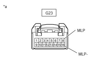
| *a | Component without harness connected
(Outer Rear View Mirror Assembly RH) |
Remove the outer rear view mirror assembly RH. ( w/o Memory)
Apply auxiliary battery voltage to the door mirror foot light and check that the light illuminates.
- OK:
w/ Memory Measurement Condition Specified Condition Auxiliary battery positive (+) → Terminal 18 (MLP)
Auxiliary battery negative (-) → Terminal 16 (MLP-)Door mirror foot light illuminates
w/o Memory Measurement Condition Specified Condition Auxiliary battery positive (+) → Terminal 8 (MLP)
Auxiliary battery negative (-) → Terminal 16 (MLP-)Door mirror foot light illuminates
- Result:
Proceed to OK NG
OK
NG
Disconnect the E38 main body ECU (multiplex network body ECU) connector.
Measure the resistance according to the value(s) in the table below.
- Standard Resistance:
w/ Memory Tester Connection Condition Specified Condition Click Location & Routing(G13,E38)Location & Routingewd_type=routing;type=c,c;code=G13,E38
Click Connector(G13)Body>Front Door Wire RH / Front Door Wire LH>Outer Rear View Mirror Assembly RHewd_type=component;type=c;code=G13;pinno=18,16
Click Connector(E38)Instrument Panel>Instrument Panel Wire / Radio Wiring Sub-Assy / Telephone Computer Wire>Multiplex Network Body ECUewd_type=component;type=c;code=E38;pinno=2
G13-18 (MLP) - E38-2 (MILE) Always Below 1 Ω G13-16 (MLP-) - Body ground Always Below 1 Ω
w/o Memory Tester Connection Condition Specified Condition Click Location & Routing(G23,E38)Location & Routingewd_type=routing;type=c,c;code=G23,E38
Click Connector(G23)Body>Front Door Wire RH / Front Door Wire LH>Outer Rear View Mirror Assembly RHewd_type=component;type=c;code=G23;pinno=8,16
Click Connector(E38)Instrument Panel>Instrument Panel Wire / Radio Wiring Sub-Assy / Telephone Computer Wire>Multiplex Network Body ECUewd_type=component;type=c;code=E38;pinno=2
G23-8 (MLP) - E38-2 (MILE) Always Below 1 Ω G23-16 (MLP-) - Body ground Always Below 1 Ω
- Result:
Proceed to OK NG
OK
NG
Disconnect the G15 outer rear view mirror assembly LH connector. (w/ Memory)
Disconnect the G24 outer rear view mirror assembly LH connector. (w/o Memory)
Disconnect the G13 outer rear view mirror assembly RH connector. (w/ Memory)
Disconnect the G23 outer rear view mirror assembly RH connector. (w/o Memory)
Disconnect the E38 main body ECU (multiplex network body ECU) connector.
Measure the resistance according to the value(s) in the table below.
- Standard Resistance:
w/ Memory Tester Connection Condition Specified Condition Click Location & Routing(G15,E38,G13)Location & Routingewd_type=routing;type=c,c,c;code=G15,E38,G13
Click Connector(G15)Body>Front Door Wire RH / Front Door Wire LH>Outer Rear View Mirror Assembly LHewd_type=component;type=c;code=G15;pinno=18
Click Connector(E38)Instrument Panel>Instrument Panel Wire / Radio Wiring Sub-Assy / Telephone Computer Wire>Multiplex Network Body ECUewd_type=component;type=c;code=E38;pinno=2
Click Connector(G13)Body>Front Door Wire RH / Front Door Wire LH>Outer Rear View Mirror Assembly RHewd_type=component;type=c;code=G13;pinno=18
G15-18 (MLP) - E38-2 (MILE) Always Below 1 Ω G13-18 (MLP) - E38-2 (MILE) Always Below 1 Ω G15-18 (MLP), G13-18 (MLP) or E38-2 (MILE) - Body ground Always 10 kΩ or higher
w/o Memory Tester Connection Condition Specified Condition Click Location & Routing(G24,E38,G23)Location & Routingewd_type=routing;type=c,c,c;code=G24,E38,G23
Click Connector(G24)Body>Front Door Wire RH / Front Door Wire LH>Outer Rear View Mirror Assembly LHewd_type=component;type=c;code=G24;pinno=8
Click Connector(E38)Instrument Panel>Instrument Panel Wire / Radio Wiring Sub-Assy / Telephone Computer Wire>Multiplex Network Body ECUewd_type=component;type=c;code=E38;pinno=2
Click Connector(G23)Body>Front Door Wire RH / Front Door Wire LH>Outer Rear View Mirror Assembly RHewd_type=component;type=c;code=G23;pinno=8
G24-8 (MLP) - E38-2 (MILE) Always Below 1 Ω G23-8 (MLP) - E38-2 (MILE) Always Below 1 Ω G24-8 (MLP), G23-8 (MLP) or E38-2 (MILE) - Body ground Always 10 kΩ or higher
- Result:
Proceed to OK NG
OK
NG