BRAKE CONTROL / DYNAMIC CONTROL SYSTEMS ELECTRONICALLY CONTROLLED BRAKE SYSTEM(for Gasoline Model) C050C14 Left Rear Wheel Speed Sensor Circuit Short to Ground or Open
DESCRIPTION
Refer to DTC C050C12
| DTC No. | Detection Item | DTC Detection Condition | Trouble Area | DTC Output from | Priority |
|---|---|---|---|---|---|
| C050C14 | Left Rear Wheel Speed Sensor Circuit Short to Ground or Open | A short or open circuit is detected in the speed sensor signal circuit for 0.12 seconds or more. | ·
Rear speed sensor LH ·
Wire harness or connector ·
Skid control sensor wire LH (No. 2 parking brake wire assembly) ·
Skid control ECU (brake actuator assembly) |
Brake/EPB | A |
WIRING DIAGRAM
PROCEDURE
Procedure1
Make sure that there is no looseness at the locking part and the connecting part of the connectors.
- OK:
The connector is securely connected.
Pre-procedure1
Disconnect the k2 rear speed sensor LH connector.
Procedure2
Check both the connector case and the terminals for deformation and corrosion.
- OK:
No deformation or corrosion.
Pre-procedure2
Turn the ignition switch to ON.
Procedure3
Measure the voltage according to the value(s) in the table below.
- Standard Voltage:
Tester Connection Condition Specified Condition Click Location & Routing(k2)Location & Routingewd_type=routing;type=c;code=k2
Click Connector(k2)Body>Parking Brake Wire Assy>Rear Speed Sensor LHewd_type=component;type=c;code=k2;pinno=2,1
k2-2 (LA+) - k2-1 (LA-) Ignition switch ON 11 to 14 V
- Result:
Proceed to OK NG
Post-procedure1
None
OK
NG
Procedure1
Make sure that there is no looseness at the locking part and the connecting part of the connectors.
- OK:
The connector is securely connected.
Pre-procedure1
Disconnect the k2 skid control sensor wire LH (No. 2 parking brake wire assembly) connector.
Disconnect the kL1 skid control sensor wire LH (No. 2 parking brake wire assembly) connector.
Procedure2
Check both the connector case and the terminals for deformation and corrosion.
- OK:
No deformation or corrosion.
Procedure3
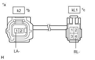
| *a | Front view of skid control sensor wire LH (No. 2 parking brake wire assembly) |
| *b | Front view of wire harness connector
(to Sensor Side Connector) |
| *c | Front view of wire harness connector
(to Vehicle Side Connector) |
Measure the resistance according to the value(s) in the table below.
- Standard Resistance:
Tester Connection Condition Specified Condition Click Location & Routing(k2,kL1)Location & Routingewd_type=routing;type=c,w;code=k2,kL1
Click Connector(k2)Body>Parking Brake Wire Assy>Rear Speed Sensor LHewd_type=component;type=c;code=k2;pinno=1
Click Connector(kL1)Body>Parking Brake Wire Assy>Parking Brake Wire Assembly LH and No. 2 Floor Wireewd_type=component;type=w;code=kL1;pinno=4
k2-1 (LA-) or kL1-4 (RL-) - Body ground and other terminals Always 10 kΩ or higher
- Result:
Proceed to OK NG
Post-procedure1
None
OK
NG
Procedure1
Make sure that there is no looseness at the locking part and the connecting part of the connectors.
- OK:
The connector is securely connected.
Pre-procedure1
Disconnect the A40 skid control ECU (brake actuator assembly) connector.
Disconnect the kL1 skid control sensor wire LH (No. 2 parking brake wire assembly) connector.
Procedure2
Check both the connector case and the terminals for deformation and corrosion.
- OK:
No deformation or corrosion.
Procedure3
Measure the resistance according to the value(s) in the table below.
- Standard Resistance:
Tester Connection Condition Specified Condition Click Location & Routing(kL1,A40)Location & Routingewd_type=routing;type=w,c;code=kL1,A40
Click Connector(kL1)Body>Parking Brake Wire Assy>Parking Brake Wire Assembly LH and No. 2 Floor Wireewd_type=component;type=w;code=kL1;pinno=4
Click Connector(A40)Engine Compartment>Engine Room Main Wire / Transmission Wire>Brake Actuator Assemblyewd_type=component;type=c;code=A40;pinno=23
kL1-4 (RL-) or A40-23 (RL-) - Body ground Always 10 kΩ or higher
- HINT:
-
The rear speed sensor LH (for 2WD) and rear speed sensor rotor LH are incorporated into the rear axle hub and bearing assembly LH.
-
If the rear speed sensor LH (for 2WD) and rear speed sensor rotor LH need to be replaced, replace the rear axle hub and bearing assembly LH.
- Result:
Proceed to OK NG
Post-procedure1
None
OK
for 2WD: Click hereDrivetrain>AXLE AND DIFFERENTIAL>REAR AXLE HUB (for 2WD)>REMOVAL202203,202303,_52,_111808,_0501217,RM1000000022EDC,202303,999999,_52,_111808,_0501217,RM100000002B3B5,
NG
Procedure1
Make sure that there is no looseness at the locking part and the connecting part of the connectors.
- OK:
The connector is securely connected.
Pre-procedure1
Disconnect the k2 skid control sensor wire LH (No. 2 parking brake wire assembly) connector.
Disconnect the kL1 skid control sensor wire LH (No. 2 parking brake wire assembly) connector.
Procedure2
Check both the connector case and the terminals for deformation and corrosion.
- OK:
No deformation or corrosion.
Procedure3
| *a | Front view of skid control sensor wire LH (No. 2 parking brake wire assembly) |
| *b | Front view of wire harness connector
(to Sensor Side Connector) |
| *c | Front view of wire harness connector
(to Vehicle Side Connector) |
Measure the resistance according to the value(s) in the table below.
- Standard Resistance:
Tester Connection Condition Specified Condition Click Location & Routing(k2,kL1)Location & Routingewd_type=routing;type=c,w;code=k2,kL1
Click Connector(k2)Body>Parking Brake Wire Assy>Rear Speed Sensor LHewd_type=component;type=c;code=k2;pinno=1
Click Connector(kL1)Body>Parking Brake Wire Assy>Parking Brake Wire Assembly LH and No. 2 Floor Wireewd_type=component;type=w;code=kL1;pinno=4
k2-1 (LA-) - kL1-4 (RL-) Always Below 1 Ω
- Result:
Proceed to OK NG
Post-procedure1
None
OK
NG
Procedure1
Make sure that there is no looseness at the locking part and the connecting part of the connectors.
- OK:
The connector is securely connected.
Pre-procedure1
Disconnect the A40 skid control ECU (brake actuator assembly) connector.
Disconnect the kL1 skid control sensor wire LH (No. 2 parking brake wire assembly) connector.
Procedure2
Check both the connector case and the terminals for deformation and corrosion.
- OK:
No deformation or corrosion.
Procedure3
Measure the resistance according to the value(s) in the table below.
- Standard Resistance:
Tester Connection Condition Specified Condition Click Location & Routing(kL1,A40)Location & Routingewd_type=routing;type=w,c;code=kL1,A40
Click Connector(kL1)Body>Parking Brake Wire Assy>Parking Brake Wire Assembly LH and No. 2 Floor Wireewd_type=component;type=w;code=kL1;pinno=4
Click Connector(A40)Engine Compartment>Engine Room Main Wire / Transmission Wire>Brake Actuator Assemblyewd_type=component;type=c;code=A40;pinno=23
kL1-4 (RL-) - A40-23 (RL-) Always Below 1 Ω
- Result:
Proceed to OK NG
Post-procedure1
None
OK
NG