M20C-FKS, M20D-FKS FUEL FUEL TANK INSTALLATION
PROCEDURE

 77654A
1.INSTALL NO. 4 FUEL TANK CUSHION
77654A
1.INSTALL NO. 4 FUEL TANK CUSHION
Install 2 new No. 4 fuel tank cushions to the fuel tank assembly.
77653A
2.INSTALL NO. 3 FUEL TANK CUSHION
Install a new No. 3 fuel tank cushion to the fuel tank assembly.
77652A
3.INSTALL NO. 2 FUEL TANK CUSHION
Install a new No. 2 fuel tank cushion to the fuel tank assembly.
77651A
4.INSTALL NO. 1 FUEL TANK CUSHION
Install 2 new No. 1 fuel tank cushions to the fuel tank assembly.
77016H
5.INSTALL FUEL RETURN VENT TUBE SUB-ASSEMBLY
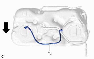
| *1 | Fuel Return Vent Tube Sub-assembly |

|
Front of the Vehicle |
Imstall the fuel return vent tube sub-assembly to the fuel tank assembly.
- NOTICE:
-
Make sure to correctly assemble the fuel return vent tube sub-assembly as shown in the illustration. If assembled incorrectly, the fuel sender gauge assembly (No. 2 fuel sender gauge assembly) may catch on the fuel return vent tube sub-assembly resulting in incorrect operation of the fuel sender gauge assembly (No. 2 fuel sender gauge assembly) and an incorrect value being displayed on the fuel gauge.
77209C
6.INSTALL FUEL TANK MAIN TUBE SUB-ASSEMBLY
Engage the clamp to install the fuel tank main tube sub-assembly to the fuel tank assembly.
77100
7.INSTALL FUEL TANK ASSEMBLY
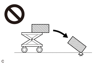
- CAUTION:
-
-
The fuel tank assembly is very heavy. Be sure to follow the procedure described in the repair manual, or the fuel tank assembly may fall off the engine lifter.
Set the fuel tank assembly on an engine lifter.
- NOTICE:
-
Using height adjustment attachments and plate lift attachments, keep the fuel tank assembly horizontal.
Using the engine lifter, slowly raise the fuel tank assembly, and then temporarily install the fuel tank assembly and 2 fuel tank band sub-assemblies with the 4 bolts.
- NOTICE:
- ·
Be careful not to drop the fuel tank assembly.
·When installing the fuel tank assembly, tilt it slightly to prevent it from interfering with the surrounding parts.
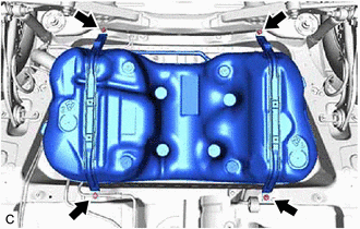
Tighten the 4 bolts in the order shown in the illustration.
- Torque:
- Specified tightening torque: : 45 N*m (459 kgf*cm, 33 ft.*lbf)

| *a | LH Side |
| *b | RH Side |
| *c | Torque Wrench Fulcrum Length |
Using SST, install the rear side of the fuel tank band sub-assembly.
- SST
- 09961-00950
- Torque:
- Specified tightening torque: : 45 N*m (459 kgf*cm, 33 ft.*lbf)
- HINT:
- ·
Calculate the torque wrench reading when changing the fulcrum length of the torque wrench.
·When using SST (fulcrum length of 150 mm (5.91 in.)) + torque wrench (fulcrum length of 180 mm (7.09 in.)): 24.5 N*m (250 kgf*cm, 18 ft.*lbf)
77210
8.CONNECT FUEL TANK FILLER PIPE ASSEMBLY
Connect the fuel tank filler pipe assembly to the fuel tank assembly.
9.CONNECT FUEL TANK BREATHER TUBE
Connect the fuel tank breather tube to the fuel tank breather tube sub-assembly.
77209C
10.CONNECT FUEL TANK MAIN TUBE SUB-ASSEMBLY
Connect the fuel tank main tube sub-assembly to the fuel pipe.
11.CONNECT FUEL TANK EVAP/VENT TUBE SUB-ASSEMBLY
Connect the fuel tank evap/vent tube sub-assembly to the fuel tank vent hose sub-assembly.
Engage the clamp.
77606
12.INSTALL NO. 1 FUEL TANK PROTECTOR SUB-ASSEMBLY
Install the No. 1 fuel tank protector sub-assembly to the fuel tank assembly with the 4 clips.
77606C
13.INSTALL NO. 2 FUEL TANK PROTECTOR
Install the No. 2 fuel tank protector with the nut.
- Torque:
- 10.5 N*m (107 kgf*cm, 8 ft.*lbf)
37100
14.INSTALL PROPELLER WITH CENTER BEARING SHAFT ASSEMBLY (for AWD)
17430
15.INSTALL TAIL EXHAUST PIPE ASSEMBLY
16.ADD FUEL
77020A
17.INSTALL FUEL SUCTION TUBE WITH PUMP AND GAUGE ASSEMBLY
77010
18.INSTALL FUEL TANK VENT TUBE ASSEMBLY
58398F
19.INSTALL NO. 1 FLOOR UNDER COVER
Tighten the clip to install the No. 1 floor under cover to the vehicle body.
Install the 3 clips and 2 bolts.
- Torque:
- Bolt : 7.5 N*m (76 kgf*cm, 66 in.*lbf)
58165C
20.INSTALL FRONT FLOOR COVER RH
Tighten the 3 clips to install the front floor cover RH to the vehicle body.
Install the 2 clips, 2 bolts and 4 screws.
- Torque:
- Bolt : 7.5 N*m (76 kgf*cm, 66 in.*lbf)
58399D
21.INSTALL NO. 2 FLOOR UNDER COVER
Tighten the 4 clips to install the No. 2 floor under cover to the vehicle body.
Install the 3 clips and 2 bolts.
- Torque:
- Bolt : 7.5 N*m (76 kgf*cm, 66 in.*lbf)
58166A
22.INSTALL FRONT FLOOR COVER LH
Tighten the 3 clips to install the front floor cover LH to the vehicle body.
Install the 3 clips, 2 bolts and 5 screws.
- Torque:
- Bolt : 7.5 N*m (76 kgf*cm, 66 in.*lbf)
51420
23.INSTALL NO. 2 ENGINE UNDER COVER ASSEMBLY