SEAT FRONT POWER SEAT CONTROL SYSTEM(w/ Memory) Front Power Seat does not Operate with Front Power Seat Switch
DESCRIPTION
Signals are input into the position control ECU assembly. The built-in ECU manages the signals received from the power seat switch and operates each motor. If the position control ECU assembly receives more than 2 motor operation signals for the same motor, the motor will be stopped. Manual operation resumes when the position control ECU assembly receives only 1 signal.
WIRING DIAGRAM
for SFTM Made
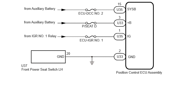
for GTMC Made

CAUTION / NOTICE / HINT
- NOTICE:
-
Inspect the fuses for circuits related to this system before performing the following procedure.
PROCEDURE
Check that each function of the power seat operates normally by using the front power seat switch LH.
- Result:
Result Proceed to All power seat functions do not operate A One or more power seat functions do not operate B
A
B
for SFTM Made: Click hereVehicle Interior>SEAT>POWER SEAT SWITCH (for SFTM Made)>INSPECTION202111,999999,_58,_111839,_0500777,RM100000001Z3ER,
for GTMC Made: Click hereVehicle Interior>SEAT>POWER SEAT SWITCH (for GTMC Made)>INSPECTION202203,999999,_58,_111839,_0525818,RM10000000229HF,
- Result:
Proceed to OK NG
OK
NG
for SFTM Made: Click hereVehicle Interior>SEAT>POWER SEAT SWITCH (for SFTM Made)>REMOVAL202203,202303,_58,_111839,_0500777,RM1000000022EHP,202303,202406,_58,_111839,_0500777,RM100000002B4XF,202406,999999,_58,_111839,_0500777,RM100000002MQQO,
for GTMC Made: Click hereVehicle Interior>SEAT>POWER SEAT SWITCH (for GTMC Made)>REMOVAL202203,202303,_58,_111839,_0525818,RM10000000229HG,202303,202406,_58,_111839,_0525818,RM100000002B4XE,202406,999999,_58,_111839,_0525818,RM100000002MQQN,
Disconnect the U33*1 or U54*2 and U35 position control ECU assembly connectors.
*1: for SFTM Made
*2: for GTMC Made
Measure the voltage according to the value(s) in the table below.
- Standard Voltage:
for SFTM Made Tester Connection Condition Specified Condition Click Location & Routing(U33,U35)Location & Routingewd_type=routing;type=c,c;code=U33,U35
Click Connector(U33)Seat>Front Seat Wire RH / Front Seat Wire LH>Position Control ECU Assembly LHewd_type=component;type=c;code=U33;pinno=3
Click Connector(U35)Seat>Front Seat Wire RH / Front Seat Wire LH>Position Control ECU Assembly LHewd_type=component;type=c;code=U35;pinno=15,1
U33-3 (+B) - Body ground Ignition switch off 11 to 14 V U35-15 (SYSB) - Body ground Ignition switch off 11 to 14 V U35-1 (IG) - Body ground Ignition switch ON 11 to 14 V U35-1 (IG) - Body ground Ignition switch off Below 1 V
| Tester Connection | Condition | Specified Condition |
|---|---|---|
|
Click Location & Routing(U54,U35)Location & Routingewd_type=routing;type=c,c;code=U54,U35 Click Connector(U54)Seat>Front Seat Wire RH / Front Seat Wire LH>Position Control ECU Assembly LHewd_type=component;type=c;code=U54;pinno=3 Click Connector(U35)Seat>Front Seat Wire RH / Front Seat Wire LH>Position Control ECU Assembly LHewd_type=component;type=c;code=U35;pinno=15,1 |
||
| U54-3 (+B) - Body ground | Ignition switch off | 11 to 14 V |
| U35-15 (SYSB) - Body ground | Ignition switch off | 11 to 14 V |
| U35-1 (IG) - Body ground | Ignition switch ON | 11 to 14 V |
| U35-1 (IG) - Body ground | Ignition switch off | Below 1 V |
- Result:
Proceed to OK NG
OK
NG
Measure the resistance according to the value(s) in the table below.
- Standard Resistance:
for SFTM Made Tester Connection Condition Specified Condition Click Location & Routing(U33)Location & Routingewd_type=routing;type=c;code=U33
Click Connector(U33)Seat>Front Seat Wire RH / Front Seat Wire LH>Position Control ECU Assembly LHewd_type=component;type=c;code=U33;pinno=2
U33-2 (GND) - Body ground Always Below 1 Ω
for GTMC Made Tester Connection Condition Specified Condition Click Location & Routing(U54)Location & Routingewd_type=routing;type=c;code=U54
Click Connector(U54)Seat>Front Seat Wire RH / Front Seat Wire LH>Position Control ECU Assembly LHewd_type=component;type=c;code=U54;pinno=2
U54-2 (GND) - Body ground Always Below 1 Ω
- Result:
Proceed to OK NG
OK
NG
Measure the resistance according to the value(s) in the table below.
- Standard Resistance:
for SFTM Made Tester Connection Condition Specified Condition Click Location & Routing(U37)Location & Routingewd_type=routing;type=c;code=U37
Click Connector(U37)Seat>Front Seat Wire RH / Front Seat Wire LH>Front Power Seat Switch LHewd_type=component;type=c;code=U37;pinno=20
U37-20 (GND) - Body ground Always Below 1 Ω
for GTMC Made Tester Connection Condition Specified Condition Click Location & Routing(U37,U35)Location & Routingewd_type=routing;type=c,c;code=U37,U35
Click Connector(U37)Seat>Front Seat Wire RH / Front Seat Wire LH>Front Power Seat Switch LHewd_type=component;type=c;code=U37;pinno=20
Click Connector(U35)Seat>Front Seat Wire RH / Front Seat Wire LH>Position Control ECU Assembly LHewd_type=component;type=c;code=U35;pinno=12
U37-20 (GND) - U35-12 (SGND) Always Below 1 Ω
- Result:
Proceed to OK NG
OK
for SFTM Made: Click hereVehicle Interior>SEAT>POWER SEAT CONTROL ECU (for SFTM Made)>REMOVAL202203,202303,_58,_111839,_0500782,RM1000000022EHU,202303,202406,_58,_111839,_0500782,RM100000002B4Y0,202406,999999,_58,_111839,_0500782,RM100000002MQQP,
for GTMC Made: Click hereVehicle Interior>SEAT>POWER SEAT CONTROL ECU (for GTMC Made)>REMOVAL202203,202303,_58,_111839,_0525817,RM10000000229H8,202303,202406,_58,_111839,_0525817,RM100000002B4XZ,202406,999999,_58,_111839,_0525817,RM100000002MQQR,
NG