SEAT FRONT POWER SEAT CONTROL SYSTEM(w/ Memory) TERMINALS OF ECU
CHECK POSITION CONTROL ECU ASSEMBLY
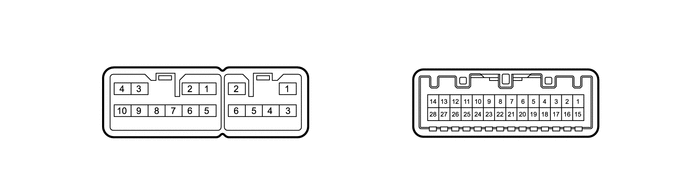
| *A | for SFTM Made | *B | for GTMC Made |
Disconnect the U33*1, U54*2 and U35 position control ECU assembly connectors.
*1: for SFTM Made
*2: for GTMC Made
Measure the voltage and resistance according to the value(s) in the table below.
- HINT:
-
Measure the values on the wire harness side with the connector disconnected.
| Tester Connection | Terminal Description | Condition | Specified Condition |
|---|---|---|---|
| U33-3 (+B) - Body ground*3
U54-3 (+B) - Body ground*4 |
Auxiliary battery power supply | Ignition switch off*1
Always*2 |
11 to 14 V |
| U35-1 (IG) - Body ground | Ignition power supply | Ignition switch off | Below 1 V |
| Ignition switch ON | 11 to 14 V | ||
| U35-15 (SYSB) - Body ground | System power source | Ignition switch off*1
Always*2 |
11 to 14 V |
| U33-2 (GND) - Body ground*3
U54-2 (GND) - Body ground*4 |
Ground | Always | Below 1 Ω |
| U35-27 (RDC) - Body ground*3
U35-27 (DBCL) - Body ground*4 |
Driver seat belt buckle switch signal | Driver seat belt unfastened | 10 kΩ or higher |
| Driver seat belt fastened | Below 1 Ω |
*1: for HV Model
*2: for Gasoline Model
*3: for SFTM Made
*4: for GTMC Made
Reconnect the U33*1, U54*2 and U35 position control ECU assembly connectors.
*1: for SFTM Made
*2: for GTMC Made
Measure the voltage and resistance according to the value (s) in the table below.
| Tester Connection | Terminal Description | Condition | Specified Condition |
|---|---|---|---|
| U33-1 (SLD+) - Body ground*1
U54-1 (SLD+) - Body ground*2 |
Slide motor signal (forward) | Slide switch off | Below 1 V |
| Slide switch on (Forward) | 11 to 14 V | ||
| U33-5 (SLD-) - Body ground*1
U54-5 (SLD-) - Body ground*2 |
Slide motor signal (rearward) | Slide switch off | Below 1 V |
| Slide switch on (Rearward) | 11 to 14 V | ||
| U33-6 (LFT+) - Body ground*1
U54-6 (LFT+) - Body ground*2 |
Lifter motor signal (upward) | Lifter switch off | Below 1 V |
| Lifter switch on (Upward) | 11 to 14 V | ||
| U34-5 (LFT-) - Body ground*1
U54-5 (LFT-) - Body ground*2 |
Lifter motor signal (downward) | Lifter switch off | Below 1 V |
| Lifter switch on (Downward) | 11 to 14 V | ||
| U33-10 (RCL+) - Body ground*1
U54-10 (RCL+) - Body ground*2 |
Reclining motor signal (forward) | Reclining switch off | Below 1 V |
| Reclining switch on (Forward) | 11 to 14 V | ||
| U34-6 (RCL-) - Body ground | Reclining motor signal (rearward) | Reclining switch off | Below 1 V |
| Reclining switch on (Rearward) | 11 to 14 V | ||
| U33-7 (FRV+) - Body ground*1
U54-7 (FRV+) - Body ground*2 |
Front vertical motor signal (upward) | Front vertical switch off | Below 1 V |
| Front vertical switch on (Upward) | 11 to 14 V | ||
| U34-4 (FRV-) - Body ground | Front vertical motor signal (downward) | Front vertical switch off | Below 1 V |
| Front vertical switch on (Downward) | 11 to 14 V | ||
| U33-9 (L+) - Body ground*1
U54-9 (L+) - Body ground*2 |
Lumbar support adjuster motor signal (forward) | Lumbar support adjuster switch off | Below 1 V |
| Lumbar support adjuster switch on (Forward) | 11 to 14 V | ||
| U34-3 (L-) - Body ground | Lumbar support adjuster motor signal (rearward) | Lumbar support adjuster switch off | Below 1 V |
| Lumbar support adjuster switch on (Rearward) | 11 to 14 V | ||
| U35-4 (H) - Body ground*1
U35-4 (LFLF) - Body ground*2 |
Front power seat switch LH (lumbar support adjuster switch (forward)) signal | Lumbar support adjuster switch off | 11 to 14 V |
| Lumbar support adjuster switch on (Forward) | Below 1 V | ||
| U35-18 (R) - Body ground*1
U35-18 (LFLR) - Body ground*2 |
Front power seat switch LH (lumbar support adjuster switch (rearward)) signal | Lumbar support adjuster switch off | 11 to 14 V |
| Lumbar support adjuster switch on (Rearward) | Below 1 V | ||
| U35-9 (SLDF) - Body ground | Front power seat switch LH (slide switch (forward)) signal | Slide switch off | 11 to 14 V |
| Slide switch on (Forward) | Below 1 V | ||
| U35-23 (SLDR) - Body ground | Front power seat switch LH (slide switch (rearward)) signal | Slide switch off | 11 to 14 V |
| Slide switch on (Rearward) | Below 1 V | ||
| U35-8 (RCLF) - Body ground | Front power seat switch LH (reclining switch (forward)) signal | Reclining switch off | 11 to 14 V |
| Reclining switch on (Forward) | Below 1 V | ||
| U35-22 (RCLR) - Body ground | Front power seat switch LH (reclining switch (rearward)) signal | Reclining switch off | 11 to 14 V |
| Reclining switch on (Rearward) | Below 1 V | ||
| U35-6 (FUP) - Body ground*1
U35-6 (FRVU) - Body ground*2 |
Front power seat switch LH (front vertical switch (upward)) signal | Front vertical switch off | 11 to 14 V |
| Front vertical switch on (Upward) | Below 1 V | ||
| U35-20 (FDWN) - Body ground*1
U35-20 (FRVD) - Body ground*2 |
Front power seat switch LH (front vertical switch (downward)) signal | Front vertical switch off | 11 to 14 V |
| Front vertical switch on (Downward) | Below 1 V | ||
| U35-7 (LUP) - Body ground*1
U35-7 (LFTU) - Body ground*2 |
Front power seat switch LH (lifter switch (upward)) signal | Lifter switch off | 11 to 14 V |
| Lifter switch on (Upward) | Below 1 V | ||
| U35-21 (LDWN) - Body ground*1
U35-21 (LFTD) - Body ground*2 |
Front power seat switch LH (lifter switch (downward)) signal | Lifter switch off | 11 to 14 V |
| Lifter switch on (Downward) | Below 1 V | ||
| U35-12 (SGND) - Body ground | Sensor ground | Always | Below 1 Ω |
*1: for SFTM Made
*2: for GTMC Made
Check for pulses according to the value (s) in the table below.
| Tester Connection | Terminal Description | Condition | Specified Condition |
|---|---|---|---|
| U35-10 (SSFV) - Body ground | Front vertical position signal | Front vertical function operating | 4.8 to 5.1 V |
| U35-11 (HALL+) - Body ground*1
U35-11 (SSRR) - Body ground*2 |
Reclining position signal | Reclining function operating | 4.8 to 5.1 V |
| U35-25 (SSRL) - Body ground | Lifter position signal | Lifter function operating | 4.8 to 5.1 V |
| U35-26 (SSRS) - Body ground | Slide position signal | Slide function operating | 4.8 to 5.1 V |
*1: for SFTM Made
*2: for GTMC Made
CHECK OUTER MIRROR CONTROL ECU ASSEMBLY LH
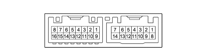
Disconnect the G22 outer mirror control ECU assembly LH connector.
Measure the voltage and resistance according to the value (s) in the table below.
- HINT:
-
Measure the values on the wire harness side with the connector disconnected.
| Tester Connection | Terminal Description | Condition | Specified Condition |
|---|---|---|---|
| G22-6 (CPUB) - G22-7 (GND) | Auxiliary battery power supply | Ignition switch off*1
Always*2 |
11 to 14 V |
| G22-14 (BDR) - G22-7 (GND) | Auxiliary battery power supply | Ignition switch off*1
Always*2 |
11 to 14 V |
| G22-5 (SIG) - G22-7 (GND) | Ignition power supply | Ignition switch ON | 11 to 14 V |
| G22-5 (SIG) - G22-7 (GND) | Ignition power supply | Ignition switch off | Below 1 V |
| G22-7 (GND) - Body ground | Ground | Always | Below 1 Ω |
*1: for HV Model
*2: for Gasoline Model
Reconnect the G22 outer mirror control ECU assembly LH connector.
Measure the voltage according to the value (s) in the table below.
| Tester Connection | Terminal Description | Condition | Specified Condition |
|---|---|---|---|
| G22-1 (MM) - G22-7 (GND) | SET switch signal for seat memory switch | SET switch on | Below 1 V |
| SET switch off | 11 to 14 V | ||
| G22-2 (M1) - G22-7 (GND) | M1 switch signal for seat memory switch | M1 switch on | Below 1 V |
| M1 switch off | 11 to 14 V | ||
| G22-3 (M2) - G22-7 (GND) | M2 switch signal for seat memory switch | M2 switch on | Below 1 V |
| M2 switch off | 11 to 14 V |
CHECK MAIN BODY ECU (MULTIPLEX NETWORK BODY ECU) AND POWER DISTRIBUTION BOX ASSEMBLY
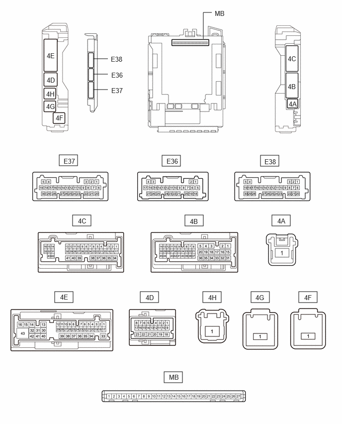
Remove the main body ECU (multiplex network body ECU) from the power distribution box assembly.
Reconnect the power distribution box assembly connectors.
Measure the voltage and resistance according to the value (s) in the table below.
| Tester Connection | Terminal Description | Condition | Specified Condition |
|---|---|---|---|
| MB-26 (BECU) - Body ground | Auxiliary battery power supply | Ignition switch off*1
Always*2 |
11 to 14 V |
| MB-27 (IGR) - Body ground | Ignition power supply | Ignition switch ON | 11 to 14 V |
| MB-27 (IGR) - Body ground | Ignition power supply | Ignition switch off | Below 1 V |
| MB-13 (GND1) - Body ground | Ground | Always | Below 1 Ω |
*1: for HV Model
*2: for Gasoline Model
Install the main body ECU (multiplex network body ECU) to power distribution box assembly.
Measure the voltage for pulses according to the value(s) in the table below.
| Tester Connection | Terminal Description | Condition | Specified Condition |
|---|---|---|---|
| 4E-3 (FLCY) - Body ground | Front door courtesy light switch assembly (LH) input | Front door LH open | Below 1 V |
| Front door LH closed | 4.7 to 5.3 V |