GF1A TRANSFER / 4WD / AWD DYNAMIC TORQUE CONTROL AWD SYSTEM C1296 ABS Malfunction
DESCRIPTION
If a malfunction in the speed sensor signal circuit or yaw rate and acceleration sensor (airbag sensor assembly) circuit occurs, the 4WD ECU assembly will output this DTC.
The airbag sensor assembly has a built-in yaw rate and acceleration sensor.
| DTC No. | Detection Item | DTC Detection Condition | Trouble Area |
|---|---|---|---|
| C1296 | ABS Malfunction | When one of the following conditions is met:
1.
Wheel speed sensor malfunction is received from skid control ECU (brake actuator assembly) 2.
Yaw rate and acceleration sensor (airbag sensor assembly) malfunction is received from skid control ECU (brake actuator assembly) |
·
Electronically controlled brake system (speed sensor circuit) ·
Skid control ECU (brake actuator assembly) ·
Yaw rate and acceleration sensor (airbag sensor assembly) circuit ·
4WD ECU assembly |
| Vehicle Condition | |||
|---|---|---|---|
| Pattern 1 | Pattern 2 | ||
| Diagnosis Condition | When communication occurs with the skid control ECU (brake actuator assembly) | ○ | ○ |
| Malfunction Status | Wheel speed sensor malfunction is received | ○ | - |
| Yaw rate and acceleration sensor (airbag sensor assembly) malfunction is received | - | ○ | |
| Detection Time | - | - | |
| Number of Trips | 1 trip | 1 trip | |
- HINT:
-
DTC will be output when conditions for either of the patterns in the table above is met.
WIRING DIAGRAM
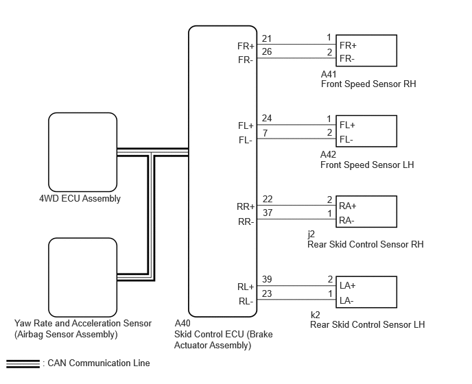
PROCEDURE
Clear the DTC.
- Chassis > Brake/EPB > Clear DTCs
- 50002 435
Turn the ignition switch off.
Turn the ignition switch to ON again.
Drive the vehicle, accelerate to a speed of 20 km/h (12 mph) or more, and check if the speed sensor DTC (electronically controlled brake system DTC) is output.
- Chassis > Brake/EPB > Trouble Codes
- 50001 435
- Result:
Result Proceed to Electronically controlled brake system DTC (speed sensor or acceleration sensor DTC) is not output A Electronically controlled brake system DTC (speed sensor or acceleration sensor DTC) is output B
- HINT:
-
When DTCs indicating a CAN communication system malfunction are output, repair the CAN communication system before repairing each corresponding sensor.
A
B
Read the value displayed on the GTS.
- Chassis > Four Wheel Drive > Data List
-
Tester Display Measurement Item Range Normal Condition Diagnostic Note FR Wheel Speed Front wheel speed sensor RH reading Min.: 0 km/h (0 mph)
Max.: 326 km/h (202 mph)0 km/h (0 mph): Vehicle stopped No large fluctuations when driving at a constant speed. FL Wheel Speed Front wheel speed sensor LH reading Min.: 0 km/h (0 mph)
Max.: 326 km/h (202 mph)0 km/h (0 mph): Vehicle stopped No large fluctuations when driving at a constant speed. RR Wheel Speed Rear wheel speed sensor RH reading Min.: 0 km/h (0 mph)
Max.: 326 km/h (202 mph)0 km/h (0 mph): Vehicle stopped No large fluctuations when driving at a constant speed. RL Wheel Speed Rear wheel speed sensor LH reading Min.: 0 km/h (0 mph)
Max.: 326 km/h (202 mph)0 km/h (0 mph): Vehicle stopped No large fluctuations when driving at a constant speed.
- Chassis > Four Wheel Drive > Data List
-
Tester Display FR Wheel Speed FL Wheel Speed RR Wheel Speed RL Wheel Speed - 50003 118 1,2,3,4
- OK:
The speed value output from the speed sensor displayed on the GTS is the same as the actual vehicle speed measured using a speedometer tester (calibrated chassis dynamometer).
- Result:
Proceed to OK NG
OK
NG
Read the value displayed on the GTS.
- Chassis > Four Wheel Drive > Data List
-
Tester Display Measurement Item Range Normal Condition Diagnostic Note Forward and Rearward G Forward and Rearward G Min.: -25.10 m/s2
Max.: 24.90 m/s2Approximately 0 +/-0.13 m/s2 while stationary Changes in proportion with acceleration during acceleration/deceleration.
- Chassis > Four Wheel Drive > Data List
-
Tester Display Forward and Rearward G - 50003 118 15
- OK:
The yaw rate and acceleration sensor (airbag sensor assembly) output value is normal.
- Result:
Proceed to OK NG
OK
NG