GF1A TRANSFER / 4WD / AWD DYNAMIC TORQUE CONTROL AWD SYSTEM C120C Linear Solenoid Power Supply System Malfunction
DESCRIPTION
This DTC is output by the 4WD ECU assembly if a malfunction occurs in the linear solenoid power supply system.
| DTC No. | Detection Item | DTC Detection Condition | Trouble Area |
|---|---|---|---|
| C120C | Linear Solenoid Power Supply System Malfunction | 1.
When the 4WD relay is on, the 4WD relay monitor remains off for 1 second or more while the voltage at the IG1 terminal is 9.5 V or more 2.
When the 4WD relay is on, the 4WD relay monitor remains off for 1 second or more while the voltage at the IG1 terminal is less than 9.5 V 3.
While the 4WD relay is off, the 4WD relay monitor remains on for 1 second or more immediately after the ignition switch is turned to ON |
·
Wire harness or connector ·
4WD ECU assembly |
| Vehicle Condition | ||||
|---|---|---|---|---|
| Pattern 1 | Pattern 2 | Pattern 3 | ||
| Diagnosis Condition | When the 4WD relay is on and the voltage at the IG1 terminal is 9.5 V or more | ○ | - | - |
| When the 4WD relay is on and the voltage at the IG1 terminal is less than 9.5 V | - | ○ | - | |
| While the 4WD relay is off | - | - | ○ | |
| Malfunction Status | The 4WD relay monitor remains off | ○ | ○ | - |
| The 4WD relay monitor remains on immediately after the ignition switch is turned to ON | - | - | ○ | |
| Detection Time | 1 second or more | 1 second or more | 1 second or more | |
| Number of Trips | 1 trip | 1 trip | 1 trip | |
- HINT:
-
DTC will be output when conditions for any of the patterns in the table above are met.
WIRING DIAGRAM
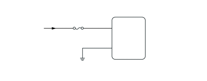
CAUTION / NOTICE / HINT
- NOTICE:
-
Inspect the fuses for circuits related to this system before performing the following inspection procedure.
PROCEDURE
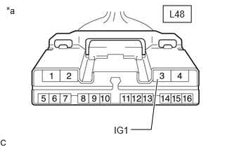
| *a | Front view of wire harness connector
(to 4WD ECU Assembly) |
Disconnect the L48 4WD ECU assembly connector.
Turn the ignition switch to ON.
Measure the voltage according to the value(s) in the table below.
- Standard Voltage:
Tester Connection Condition Specified Condition Click Location & Routing(L48)Location & Routingewd_type=routing;type=c;code=L48
Click Connector(L48)Body>No. 2 Floor Wire>4WD ECU Assemblyewd_type=component;type=c;code=L48;pinno=3
L48-3 (IG1) - Body ground Ignition switch ON 11 to 14 V
- Result:
Proceed to OK NG
OK
NG
Turn the ignition switch off.
Measure the resistance according to the value(s) in the table below.
- Standard Resistance:
Tester Connection Condition Specified Condition Click Location & Routing(L48)Location & Routingewd_type=routing;type=c;code=L48
Click Connector(L48)Body>No. 2 Floor Wire>4WD ECU Assemblyewd_type=component;type=c;code=L48;pinno=4
L48-4 (GND) - Body ground Always Below 1 Ω
- Result:
Proceed to OK NG
OK
NG
Clear the DTC.
- Chassis > Four Wheel Drive > Clear DTCs
- 50002 118
Turn the ignition switch to ON.
Check that no DTCs other than DTC C120C have been output.
- Chassis > Four Wheel Drive > Trouble Codes
- 50001 118
- Result:
Result Proceed to DTCs other than DTC C120C are not output A DTCs other than DTC C120C are output B
A
B