GF1A TRANSFER / 4WD / AWD TRANSFER ASSEMBLY INSTALLATION
PROCEDURE

 36100
1.INSTALL TRANSFER ASSEMBLY
36100
1.INSTALL TRANSFER ASSEMBLY
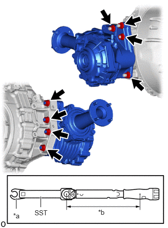
| *a | 17 mm Union Nut Wrench |
| *b | Torque Wrench Fulcrum Length |
Using SST and a 17 mm union nut wrench, install the transfer assembly to the continuously variable transaxle assembly with the 8 nuts.
- SST
- 09961-00950
- Torque:
- Specified Tightening Torque : 68.6 N*m (700 kgf*cm, 51 ft.*lbf)
- HINT:
- ·
Calculate the torque wrench reading when changing the fulcrum length of the torque wrench.
·When using a 17 mm union nut wrench (fulcrum length of 30 mm (1.18 in.)) + SST (fulcrum length of 150 mm (5.91 in.)) + torque wrench (fulcrum length of 255 mm (10.04 in.)):
40.2 N*m (410 kgf*cm, 30 ft.*lbf)
12303
2.INSTALL REAR ENGINE MOUNTING BRACKET SUB-ASSEMBLY
12371A
3.INSTALL REAR ENGINE MOUNTING INSULATOR
37109
4.INSTALL NO. 1 PROPELLER SHAFT HEAT INSULATOR BRACKET SUB-ASSEMBLY

Install the No. 1 propeller shaft heat insulator bracket sub-assembly with the 2 bolts.
- Torque:
- 25 N*m (255 kgf*cm, 18 ft.*lbf)
- HINT:
-
Tightening order: Temporarily tighten bolt (A) → Fully tighten bolt (B) → Fully tighten bolt (A)
37117
5.INSTALL PROPELLER SHAFT HEAT INSULATOR
30400
6.INSTALL CONTINUOUSLY VARIABLE TRANSAXLE ASSEMBLY