RM38N0EC
_58
Vehicle Interior
_111832
THEFT DETERRENT / KEYLESS ENTRY
_0509386
THEFT DETERRENT SYSTEM
J
THEFT DETERRENT / KEYLESS ENTRY THEFT DETERRENT SYSTEM Power Source Circuit
DESCRIPTION
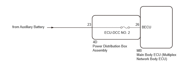
Based on changes in the power source voltage, the main body ECU (multiplex network body ECU) can detect if the auxiliary battery has been disconnected and reconnected.
WIRING DIAGRAM
4.156,1.219 5.448,1.396
1.292,0.177
10
false
ECU-DCC NO. 2
3.688,1.76 5.083,2.156
1.396,0.396
10
false
Power Distribution Box Assembly
3.479,0.896 3.875,1.198
0.396,0.302
10
false
23
5.438,2.104 7.073,2.563
1.635,0.458
10
false
Main Body ECU (Multiplex Network Body ECU)
5.438,1.938 5.917,2.115
0.479,0.177
10
false
MB
5.396,0.896 5.708,1.094
0.313,0.198
10
false
26
5.646,1 6.26,1.198
0.615,0.198
10
false
BECU
0.49,0.99 2.073,1.177
1.583,0.188
10
false
from Auxiliary Battery
3.698,1.594 4.063,1.833
0.365,0.24
10
false
4D
CAUTION / NOTICE / HINT
- NOTICE:
- ·
Before replacing the main body ECU (multiplex network body ECU), refer to Service Bulletin.
·Inspect the fuses for circuits related to this system before performing the following procedure.
PROCEDURE
1.CHECK HARNESS AND CONNECTOR (POWER SUPPLY)
a.
Disconnect the 4D power distribution box assembly connector.
b.
Measure the voltage according to the value(s) in the table below.
- Standard Voltage:
Tester Connection Condition Specified Condition 4D-23 - Body ground Ignition switch off*1
Always*28.5 V or higher
*1: for HV Model
*2: for Gasoline Model
- Result:
Proceed to OK NG
OK
2.INSPECT POWER DISTRIBUTION BOX ASSEMBLY
NG
REPAIR OR REPLACE HARNESS OR CONNECTOR
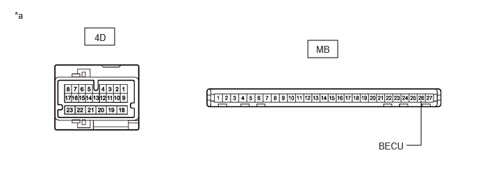
2.INSPECT POWER DISTRIBUTION BOX ASSEMBLY
a.
Remove the main body ECU (multiplex network body ECU).
1.271,0.417 1.719,0.677
0.448,0.26
4.615,0.604 5.063,0.865
0.448,0.26
6.094,2.177 6.313,2.177
6.313,2.177 6.313,1.51
false
0.219,0.146 0.531,0.344
0.313,0.198
10
false
*a
1.417,0.479 1.729,0.677
0.313,0.198
10
false
4D
4.74,0.656 5.052,0.854
0.313,0.198
10
false
MB
5.677,2.104 6.26,2.385
0.583,0.281
10
false
BECU
| *a | Component without harness connected
(Power Distribution Box Assembly) |
- | - |
b.
Measure the resistance according to the value(s) in the table below.
- Standard Resistance:
Tester Connection Condition Specified Condition 4D-23 - MB-26 (BECU) Always Below 1 Ω
- Result:
Proceed to OK NG
OK
REPLACE MAIN BODY ECU (MULTIPLEX NETWORK BODY ECU)
NG
REPLACE POWER DISTRIBUTION BOX ASSEMBLY