MIRROR (EXT) POWER MIRROR CONTROL SYSTEM(w/ Memory) TERMINALS OF ECU
CHECK OUTER MIRROR CONTROL ECU ASSEMBLY (DRIVER DOOR)
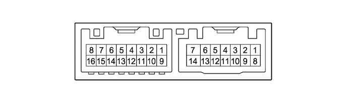
Disconnect the G22 outer mirror control ECU assembly (driver door) connector.
Measure the voltage and resistance according to the value(s) in the table below.
- HINT:
-
Measure the values on the wire harness side with the connector disconnected.
| Terminal No. (Symbol) | Terminal Description | Condition | Specified Condition |
|---|---|---|---|
| G22-14 (BDR) - Body ground | +B power supply | Ignition switch off | 11 to 14 V |
| G22-6 (CPUB) - Body ground | +B power supply | Ignition switch off | 11 to 14 V |
| G22-5 (SIG) - Body ground | Ignition power supply | Ignition switch off → ON | Below 1 V → 11 to 14 V |
| G22-7 (GND) - Body ground | Ground | Always | Below 1 Ω |
Reconnect the G22 outer mirror control ECU assembly (driver door) connector.
Measure the voltage according to the value(s) in the table below.
| Terminal No. (Symbol) | Terminal Description | Condition | Specified Condition |
|---|---|---|---|
| G21-3 (MR+) - Body ground | Power retract mirror motor drive voltage | Outer rear view mirror assembly (driver door) being retracted | 11 to 14 V |
| Outer rear view mirror assembly (driver door) stopped | Below 1 V | ||
| G21-11 (MR-) - Body ground | Power retract mirror motor drive voltage | Outer rear view mirror assembly (driver door) returning | 11 to 14 V |
| Outer rear view mirror assembly (driver door) stopped | Below 1 V | ||
| G21-1 (LMVR) - G21-10 (LM+R) | Vertical mirror motor drive voltage | Driver door mirror surface moving upward → stopped | 11 to 14 V → Below 1 V |
| G21-10 (LM+R) - G21-1 (LMVR) | Vertical mirror motor drive voltage | Driver door mirror surface moving downward → stopped | 11 to 14 V → Below 1 V |
| G21-10 (LM+R) - G21-9 (LMHR) | Horizontal mirror motor drive voltage | Driver door mirror surface moving right → stopped | 11 to 14 V → Below 1 V |
| G21-9 (LMHR) - G21-10 (LM+R) | Horizontal mirror motor drive voltage | Driver door mirror surface moving left → stopped | 11 to 14 V → Below 1 V |
| G21-5 (LVC) - G21-14 (LE1) | Mirror position sensor power supply | Ignition switch ON | 4.55 to 5.45 V |
| Ignition switch off | Below 1 V | ||
| G21-6 (VSSR) - G22-7 (GND) | Mirror position sensor signal | Ignition switch ON | 0 to 5 V |
| G21-13 (HSSR) - G22-7 (GND) | Mirror position sensor signal | Ignition switch ON | 0 to 5 V |
| G22-3 (M2) - G22-7 (GND) | M2 switch signal for seat memory switch | M2 switch on | Below 1 V |
| M2 switch off | 11 to 14 V | ||
| G22-2 (M1) - G22-7 (GND) | M1 switch signal for seat memory switch | M1 switch on | Below 1 V |
| M1 switch off | 11 to 14 V | ||
| G22-1 (MM) - G22-7 (GND) | SET switch signal for seat memory switch | SET switch on | Below 1 V |
| SET switch off | 11 to 14 V | ||
| G21-4 (HTR+) - G21-12 (HTR-) | Mirror heater relay drive voltage | Mirror heater switch (rear window defogger switch) on | 11 to 14 V |
CHECK OUTER MIRROR CONTROL ECU ASSEMBLY (FRONT PASSENGER DOOR)
Disconnect the G20 outer mirror control ECU assembly (front passenger door) connector.
Measure the voltage and resistance according to the value(s) in the table below.
- HINT:
-
Measure the values on the wire harness side with the connector disconnected.
| Terminal No. (Symbol) | Terminal Description | Condition | Specified Condition |
|---|---|---|---|
| G20-14 (BDR) - Body ground | +B power supply | Ignition switch off | 11 to 14 V |
| G20-6 (CPUB) - Body ground | +B power supply | Ignition switch off | 11 to 14 V |
| G20-5 (SIG) - Body ground | Ignition power supply | Ignition switch off → ON | Below 1 V → 11 to 14 V |
| G20-7 (GND) - Body ground | Ground | Always | Below 1 Ω |
Reconnect the G20 outer mirror control ECU assembly (front passenger door) connector.
Measure the voltage according to the value(s) in the table below.
| Terminal No. (Symbol) | Terminal Description | Condition | Specified Condition |
|---|---|---|---|
| G19-3 (MR+) - Body ground | Power retract mirror motor drive voltage | Outer rear view mirror assembly (front passenger door) being retracted | 11 to 14 V |
| Outer rear view mirror assembly (front passenger door) stopped | Below 1 V | ||
| G19-11 (MR-) - Body ground | Power retract mirror motor drive voltage | Outer rear view mirror assembly (front passenger door) returning | 11 to 14 V |
| Outer rear view mirror assembly (front passenger door) stopped | Below 1 V | ||
| G19-1 (RMVR) - G19-10 (RM+R) | Vertical mirror motor drive voltage | Front passenger door mirror surface moving upward → stopped | 11 to 14 V → Below 1 V |
| G19-10 (RM+R) - G19-1 (RMVR) | Vertical mirror motor drive voltage | Front passenger door mirror surface moving downward → stopped | 11 to 14 V → Below 1 V |
| G19-10 (RM+R) - G19-9 (RMHR) | Horizontal mirror motor drive voltage | Front passenger door mirror surface moving right → stopped | 11 to 14 V → Below 1 V |
| G19-9 (RMHR) - G19-10 (RM+R) | Horizontal mirror motor drive voltage | Front passenger door mirror surface moving left → stopped | 11 to 14 V → Below 1 V |
| G19-5 (RVC) - G19-14 (RE1) | Mirror position sensor power supply | Ignition switch ON | 4.55 to 5.45 V |
| Ignition switch off | Below 1 V | ||
| G19-6 (VSSR) - G20-7 (GND) | Mirror position sensor signal | Ignition switch ON | 0 to 5 V |
| G19-13 (HSSR) - G20-7 (GND) | Mirror position sensor signal | Ignition switch ON | 0 to 5 V |
| G19-4 (HTR+) - G19-12 (HTR-) | Mirror heater relay drive voltage | Mirror heater switch (rear window defogger switch) on | 11 to 14 V |
CHECK MAIN BODY ECU (MULTIPLEX NETWORK BODY ECU) AND POWER DISTRIBUTION BOX ASSEMBLY
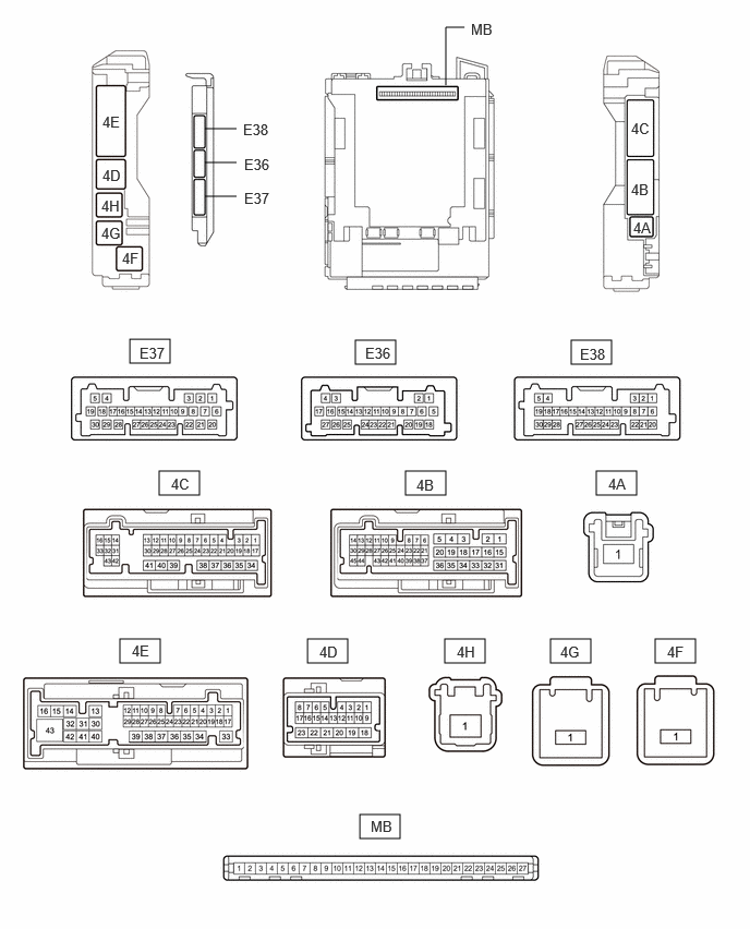
Disconnect the power distribution box assembly and main body ECU (multiplex network body ECU) connectors.
Reconnect the power distribution box assembly connectors.
Measure the resistance and voltage according to the value(s) in the table below.
| Terminal No. (Symbol) | Terminal Description | Condition | Specified Condition |
|---|---|---|---|
| MB-26 (BECU) - Body ground | Auxiliary battery power supply | Ignition switch off | 11 to 14 V |
| MB-27 (IGR) - Body ground | Ignition power supply (IG signal) | Ignition switch ON | 11 to 14 V |
| Ignition switch off | Below 1 V | ||
| MB-13 (GND1) - Body ground | Ground | Always | Below 1 Ω |
| MB-14 (GND2) - Body ground | Ground | Always | Below 1 Ω |
Connect the main body ECU (multiplex network body ECU) connectors.
Measure the voltage according to the value(s) in the table below.
| Tester Connection | Terminal Description | Condition | Specified Condition |
|---|---|---|---|
| E38-22 (MIRB) - E38-21 (MIRE) | Mirror adjust switch signal | ·
Ignition switch ACC ·
Mirror select switch L or R ·
Mirror adjust switch up |
Below 1.7 V |
·
Ignition switch ACC ·
Mirror select switch L or R ·
Mirror adjust switch right |
Below 2.7 V | ||
·
Ignition switch ACC ·
Mirror select switch L or R ·
Mirror adjust switch down |
Below 3.5 V | ||
·
Ignition switch ACC ·
Mirror select switch L or R ·
Mirror adjust switch left |
Below 4 V | ||
·
Ignition switch ACC ·
Mirror select switch L or R ·
Mirror adjust switch off |
3.8 to 5 V | ||
| E38-20 (MIRS) - E38-21 (MIRE) | Mirror select switch signal | ·
Ignition switch ACC ·
Mirror select switch L |
Below 2 V |
·
Ignition switch ACC ·
Mirror select switch R |
Below 1 V | ||
·
Ignition switch ACC ·
Mirror select switch off |
3.8 to 5 V | ||
| E36-27 (RET) - E38-21 (MIRE) | Retractable outer mirror switch signal | ·
Ignition switch ACC ·
Retractable outer mirror switch on outer mirror switch assembly not in retract position. |
11 to 14 V |
·
Ignition switch ACC ·
Retractable outer mirror switch on outer mirror switch assembly in retract position. |
Below 1 V | ||
| E36-26 (AMR) - E38-21 (MIRE) | Retractable outer mirror switch signal | ·
Ignition switch ACC ·
Retractable outer mirror switch on outer mirror switch assembly not in auto retract position. |
11 to 14 V |
·
Ignition switch ACC ·
Retractable outer mirror switch on outer mirror switch assembly in auto retract position. |
Below 1 V |