SLIDING ROOF / CONVERTIBLE PANORAMIC FIXED MOONROOF WITH ONE-TOUCH FROSTED GLASS CONTROL SYSTEM B27514B Light Control Glass Noise Filter Over Temperature
DESCRIPTION
When the main body ECU (multiplex network body ECU) detects a collision or high circuit temperature malfunction, the system enters fail-safe mode and stores this DTC.
| DTC No. | Detection Item | DTC Detection Condition | Trouble Area | DTC Output from |
|---|---|---|---|---|
| B27514B | Light Control Glass Noise Filter Over Temperature | ·
Open or short in GSW circuit of main body ECU (multiplex network body ECU) ·
Malfunction in LIB1 circuit of main body ECU (multiplex network body ECU) |
·
Main body ECU (Multiplex network body ECU) ·
Power distribution box assembly ·
Airbag sensor assembly ·
Noise filter ·
Wire harness or connector |
Main Body |
WIRING DIAGRAM
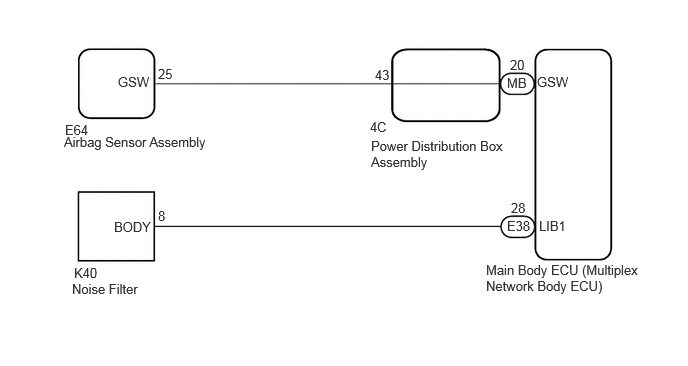
CAUTION / NOTICE / HINT
- CAUTION:
-
After performing a procedure, make sure to disconnect the cable from the auxiliary battery terminal to clear the DTCs.
- NOTICE:
-
Before replacing the main body ECU (multiplex network body ECU), refer to Service Bulletin.
PROCEDURE
Clear the DTCs.
- Body Electrical > Main Body > Clear DTCs
- 50002 449
Check for DTCs.
- Body Electrical > Main Body > Trouble Codes
- 50001 449
- Result:
Result Proceed to Only B27514B is output A B27514B and B124300 are output B
A
B
Pre-procedure1
Disconnect the K40 noise filter connector.
Disconnect the E38 main body ECU (multiplex network body ECU) connector.
Procedure1
Measure the resistance according to the value(s) in the table below.
- Standard Resistance:
Tester Connection Condition Specified Condition Click Location & Routing(E38,K40)Location & Routingewd_type=routing;type=c,c;code=E38,K40
Click Connector(E38)Instrument Panel>Instrument Panel Wire / Radio Wiring Sub-Assy / Telephone Computer Wire>Multiplex Network Body ECUewd_type=component;type=c;code=E38;pinno=28
Click Connector(K40)Body>Floor Wire>Noise Filterewd_type=component;type=c;code=K40;pinno=8
E38-28 (LIB1) - K40-8 (BODY) Always Below 1 Ω E38-28 (LIB1) or K40-8 (BODY) - Body ground Always 10 kΩ or higher
- Result:
Proceed to OK NG
Post-procedure1
None
OK
NG
Pre-procedure1
Reconnect the K40 noise filter connector.
Reconnect the E38 main body ECU (multiplex network body ECU) connector.
Procedure1
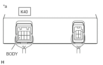
| *a | Component with harness connected
(Noise Filter) |
Measure the voltage according to the value(s) in the table below.
- Standard Voltage:
Tester Connection Condition Specified Condition Click Location & Routing(K40)Location & Routingewd_type=routing;type=c;code=K40
Click Connector(K40)Body>Floor Wire>Noise Filterewd_type=component;type=c;code=K40;pinno=8
K40-8 (BODY) - Body ground Ignition switch ON, dimmable panoramic roof glass switch on 2 to 14 V
- Result:
Proceed to OK NG
Post-procedure1
None
OK
NG