METER / GAUGE / DISPLAY METER / GAUGE SYSTEM(for TFT Meter Type) B150013 Fuel Sender Circuit Open B150113 Sub Fuel Sender Circuit Open
DESCRIPTION
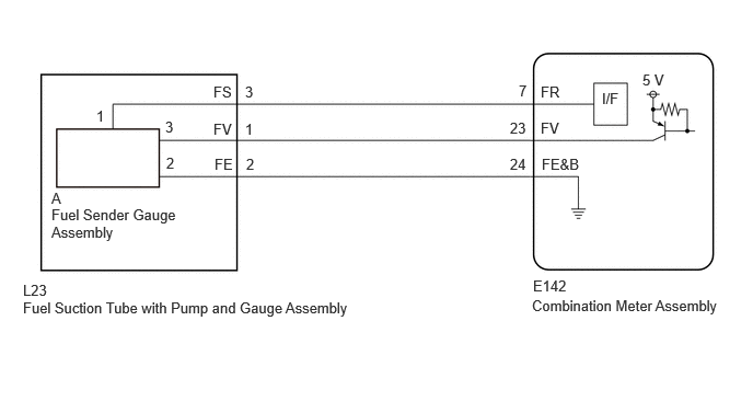
FOR HV MODEL
The fuel sender gauge assembly is connected to the combination meter assembly via direct line. If there is an open or short in the direct line, the combination meter assembly stores DTC B150013.
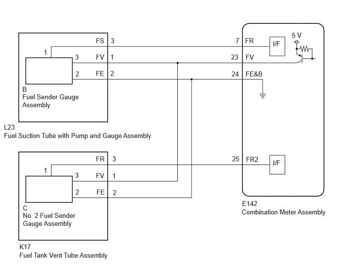
FOR GASOLINE MODEL
The fuel sender gauge assembly and No. 2 fuel sender gauge assembly are connected to the combination meter assembly via direct line. If there is an open or short in the direct line, the combination meter assembly stores DTC B150013 or B150113.
| DTC No. | Detection Item | DTC Detection Condition | Trouble Area | DTC Output from | Priority |
|---|---|---|---|---|---|
| B150013 | Fuel Sender Circuit Open | Diagnosis Condition:
·
The Ignition switch is ON ·
IG power source voltage is 9.5 V or more Malfunction Status: ·
Voltage signal from fuel sender gauge assembly is 0.2 V or less ·
Voltage signal from fuel sender gauge assembly is 4.7 V or more Malfunction Time: 10 seconds or more |
·
Harness or connector ·
Fuel sender gauge assembly ·
Fuel suction tube with pump and gauge assembly ·
Combination meter assembly |
Combination Meter | A |
| B150113 | Sub Fuel Sender Circuit Open | Diagnosis Condition:
·
The Ignition switch is ON ·
IG power source voltage is 9.5 V or more Malfunction Status: ·
Voltage signal from fuel sender gauge assembly is 0.2 V or less ·
Voltage signal from fuel sender gauge assembly is 4.7 V or more Malfunction Time: 10 seconds or more |
·
Harness or connector ·
Fuel sender gauge assembly ·
Fuel suction tube with pump and gauge assembly ·
Combination meter assembly |
Combination Meter | A |
WIRING DIAGRAM
FOR HV MODEL
FOR GASOLINE MODEL
CAUTION / NOTICE / HINT
- NOTICE:
- ·
When replacing the combination meter assembly, always replace it with a new one. If a combination meter assembly which was installed to another vehicle is used, the information stored in it will not match the information from the vehicle and a DTC may be stored.
·When replacing the combination meter assembly, update the ECU security key.
PROCEDURE
Check for DTCs.
- Body Electrical > Combination Meter > Trouble Codes
- 50001 409
- Result:
Result Proceed to Only B150013 is output A Only B150113 is output B B150013 and B150113 are output C
A
B
C
Choose the model to be inspected.
- Result:
Result Proceed to for HV Model A for Gasoline Model B
A
B
Read the Data List according to the display on the GTS.
- Body Electrical > Combination Meter > Data List
-
Tester Display Measurement Item Range Normal Condition Diagnostic Note Fuel Input Fuel level input Min.: 0.00 L, Max.: 655.35 L or Unset ·Fuel receiver gauge indicates F: 47.66 L
·Fuel receiver gauge indicates 3/4: 37.58 L
·Fuel receiver gauge indicates 1/2: 27.50 L
·Fuel receiver gauge indicates 1/4: 13.75 L
·Fuel receiver gauge indicates E: 5.50 L
The detected value of the fuel sender gauge assembly is displayed.
- Body Electrical > Combination Meter > Data List
-
Tester Display Fuel Input - 50003 409 20
- Result:
Result Proceed to Fuel level data can be displayed on the GTS A Fuel level data cannot be displayed on the GTS B
A
B
- Result:
Proceed to OK NG
OK
NG
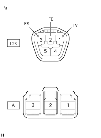
| *a | Component without harness connected
(Fuel Suction Tube with Pump and Gauge Assembly) |
Measure the resistance according to the value(s) in the table below.
- Standard Resistance:
Tester Connection Condition Specified Condition Click Location & Routing(L23)Location & Routingewd_type=routing;type=c;code=L23
Click Connector(L23)Body>No. 2 Floor Wire>Fuel Suction Tube with Pump and Gage Assemblyewd_type=component;type=c;code=L23;pinno=1,2,3
L23-1 (FV) - A-3 Always Below 1 Ω L23-2 (FE) - A-2 Always Below 1 Ω L23-3 (FS) - A-1 Always Below 1 Ω L23-1 (FV) - L23-2 (FE)
or
A-3 - A-2Always 10 kΩ or higher L23-1 (FV) - L23-3 (FS)
or
A-3 - A-1Always 10 kΩ or higher L23-2 (FE) - L23-3 (FS)
or
A-2 - A-1Always 10 kΩ or higher
- Result:
Proceed to OK NG
OK
NG
Pre-procedure1
Disconnect the E142 combination meter assembly connector.
Procedure1
Measure the resistance according to the value(s) in the table below.
- Standard Resistance:
Tester Connection Condition Specified Condition Click Location & Routing(L23,E142)Location & Routingewd_type=routing;type=c,c;code=L23,E142
Click Connector(L23)Body>No. 2 Floor Wire>Fuel Suction Tube with Pump and Gage Assemblyewd_type=component;type=c;code=L23;pinno=1,2,3
Click Connector(E142)Instrument Panel>Instrument Panel Wire / Radio Wiring Sub-Assy / Telephone Computer Wire>Combination Meter Assemblyewd_type=component;type=c;code=E142;pinno=23,24,7
L23-1 (FV) -E142-23 (FV) Always Below 1 Ω L23-2 (FE) -E142-24 (FE&B) Always Below 1 Ω L23-3 (FS) -E142-7 (FR) Always Below 1 Ω L23-1 (FV) or E142-23 (FV) - Body ground Always 10 kΩ or higher L23-3 (FS) or E142-7 (FR) - Body ground Always 10 kΩ or higher
- Result:
Proceed to OK NG
Post-procedure1
None
OK
NG
Read the Data List according to the display on the GTS.
- Body Electrical > Combination Meter > Data List
-
Tester Display Measurement Item Range Normal Condition Diagnostic Note Fuel Input Fuel level input Min.: 0.00 L, Max.: 655.35 L or Unset ·Fuel receiver gauge indicates F: 47.13 L*
·Fuel receiver gauge indicates 3/4: 37.66 L*
·Fuel receiver gauge indicates 1/2: 27.11 L
·Fuel receiver gauge indicates 1/4: 13.75 L
·Fuel receiver gauge indicates E: 5.71 L
The detected value of the fuel sender gauge assembly is displayed.
*: Combined value of "Fuel Input" and "Sub Fuel Input"
- Body Electrical > Combination Meter > Data List
-
Tester Display Fuel Input - 50003 409 20
- Result:
Result Proceed to Fuel level data can be displayed on the GTS A Fuel level data cannot be displayed on the GTS B
A
B
- Result:
Proceed to OK NG
OK
NG
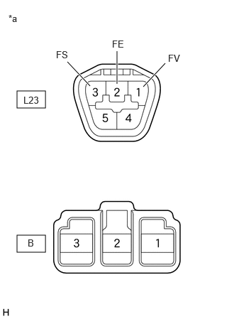
| *a | Component without harness connected
(Fuel Suction Tube with Pump and Gauge Assembly) |
Measure the resistance according to the value(s) in the table below.
- Standard Resistance:
Tester Connection Condition Specified Condition Click Location & Routing(L23)Location & Routingewd_type=routing;type=c;code=L23
Click Connector(L23)Body>No. 2 Floor Wire>Fuel Suction Tube with Pump and Gage Assemblyewd_type=component;type=c;code=L23;pinno=1,2,3
L23-1 (FV) - B-3 Always Below 1 Ω L23-2 (FE) - B-2 Always Below 1 Ω L23-3 (FS) - B-1 Always Below 1 Ω
- Result:
Proceed to OK NG
OK
NG
Pre-procedure1
Disconnect the E142 combination meter assembly connector.
Procedure1
Measure the resistance according to the value(s) in the table below.
- Standard Resistance:
Tester Connection Condition Specified Condition Click Location & Routing(L23,E142)Location & Routingewd_type=routing;type=c,c;code=L23,E142
Click Connector(L23)Body>No. 2 Floor Wire>Fuel Suction Tube with Pump and Gage Assemblyewd_type=component;type=c;code=L23;pinno=1,2,3
Click Connector(E142)Instrument Panel>Instrument Panel Wire / Radio Wiring Sub-Assy / Telephone Computer Wire>Combination Meter Assemblyewd_type=component;type=c;code=E142;pinno=23,24,7
L23-1 (FV) - E142-23 (FV) Always Below 1 Ω L23-2 (FE) - E142-24 (FE&B) Always Below 1 Ω L23-3 (FS) - E142-7 (FR) Always Below 1 Ω L23-3 (FS) or E142-7 (FR) - Body ground Always 10 kΩ or higher
- Result:
Proceed to OK NG
Post-procedure1
None
OK
NG
Read the Data List according to the display on the GTS.
- Body Electrical > Combination Meter > Data List
-
Tester Display Measurement Item Range Normal Condition Diagnostic Note Sub Fuel Input Fuel level input Min.: 0 L, Max.: 655.35 L or Unset ·Fuel receiver gauge indicates F: 47.13 L*
·Fuel receiver gauge indicates 3/4: 37.66 L*
·Fuel receiver gauge indicates 1/2: 28.18 L
The detected value of the No. 2 fuel sender gauge assembly is displayed.
*: Combined value of "Fuel Input" and "Sub Fuel Input"
- Body Electrical > Combination Meter > Data List
-
Tester Display Sub Fuel Input - 50003 409 21
- Result:
Result Proceed to Fuel level data can be displayed on the GTS A Fuel level data cannot be displayed on the GTS B
A
B
- Result:
Proceed to OK NG
OK
NG
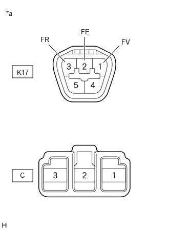
| *a | Component without harness connected
(Fuel Tank Vent Tube Assembly) |
Measure the resistance according to the value(s) in the table below.
- Standard Resistance:
Tester Connection Condition Specified Condition Click Location & Routing(K17)Location & Routingewd_type=routing;type=c;code=K17
Click Connector(K17)Body>Floor Wire>Fuel Tank Vent Tube Assemblyewd_type=component;type=c;code=K17;pinno=1,2,3
K17-1 (FV) - C-3 Always Below 1 Ω K17-2 (FE) - C-2 Always Below 1 Ω K17-3 (FR) - C-1 Always Below 1 Ω
- Result:
Proceed to OK NG
OK
NG
Pre-procedure1
Disconnect the E142 combination meter assembly connector.
Procedure1
Measure the resistance according to the value(s) in the table below.
- Standard Resistance:
Tester Connection Condition Specified Condition Click Location & Routing(K17,E142)Location & Routingewd_type=routing;type=c,c;code=K17,E142
Click Connector(K17)Body>Floor Wire>Fuel Tank Vent Tube Assemblyewd_type=component;type=c;code=K17;pinno=1,2,3
Click Connector(E142)Instrument Panel>Instrument Panel Wire / Radio Wiring Sub-Assy / Telephone Computer Wire>Combination Meter Assemblyewd_type=component;type=c;code=E142;pinno=23,24,25
K17-1 (FV) - E142-23 (FV) Always Below 1 Ω K17-2 (FE) - E142-24 (FE&B) Always Below 1 Ω K17-3 (FR) - E142-25 (FR2) Always Below 1 Ω K17-3 (FR) or E142-25 (FR2) - Body ground Always 10 kΩ or higher
- Result:
Proceed to OK NG
Post-procedure1
None
OK
NG
Read the Data List according to the display on the GTS.
- Body Electrical > Combination Meter > Data List
-
Tester Display Measurement Item Range Normal Condition Diagnostic Note Fuel Input Fuel level input Min.: 0 L, Max.: 655.34 L or Unset ·Fuel receiver gauge indicates F: 47.13 L*
·Fuel receiver gauge indicates 3/4: 37.66 L*
·Fuel receiver gauge indicates 1/2: 27.11 L
·Fuel receiver gauge indicates 1/4: 13.75 L
·Fuel receiver gauge indicates E: 5.71 L
The detected value of the fuel sender gauge assembly is displayed. Sub Fuel Input Fuel level input Min.: 0 L, Max.: 655.34 L or Unset ·Fuel receiver gauge indicates F: 47.13 L*
·Fuel receiver gauge indicates 3/4: 37.66 L*
·Fuel receiver gauge indicates 1/2: 28.18 L
The detected value of the No. 2 fuel sender gauge assembly is displayed.
*: Combined value of "Fuel Input" and "Sub Fuel Input"
- Body Electrical > Combination Meter > Data List
-
Tester Display Fuel Input Sub Fuel Input - 50003 409 20,21
- Result:
Result Proceed to Fuel level data can be displayed on the GTS A Fuel level data cannot be displayed on the GTS B
A
B
- Result:
Proceed to OK NG
OK
NG
| *a | Component without harness connected
(Fuel Suction Tube with Pump and Gauge Assembly) |
Measure the resistance according to the value(s) in the table below.
- Standard Resistance:
Tester Connection Condition Specified Condition Click Location & Routing(L23)Location & Routingewd_type=routing;type=c;code=L23
Click Connector(L23)Body>No. 2 Floor Wire>Fuel Suction Tube with Pump and Gage Assemblyewd_type=component;type=c;code=L23;pinno=1,2,3
L23-1 (FV) - L23-2 (FE)
or
B-3 - B-2Always 10 kΩ or higher L23-1 (FV) - L23-3 (FS)
or
B-3 - B-1Always 10 kΩ or higher L23-2 (FE) - L23-3 (FS)
or
B-2 - B-1Always 10 kΩ or higher
- Result:
Proceed to OK NG
OK
NG
- Result:
Proceed to OK NG
OK
NG
| *a | Component without harness connected
(Fuel Tank Vent Tube Assembly) |
Measure the resistance according to the value(s) in the table below.
- Standard Resistance:
Tester Connection Condition Specified Condition Click Location & Routing(K17)Location & Routingewd_type=routing;type=c;code=K17
Click Connector(K17)Body>Floor Wire>Fuel Tank Vent Tube Assemblyewd_type=component;type=c;code=K17;pinno=1,3,2
K17-1 (FV) - K17-3 (FR)
or
C-3 - C-1Always 10 kΩ or higher K17-1 (FV) - K17-2 (FE)
or
C-3 - C-2Always 10 kΩ or higher K17-2 (FE) - K17-3 (FR)
or
C-2 - C-1Always 10 kΩ or higher
- Result:
Proceed to OK NG
OK
NG
Pre-procedure1
Disconnect the E142 combination meter assembly connector.
Procedure1
Measure the resistance according to the value(s) in the table below.
- Standard Resistance:
Tester Connection Condition Specified Condition Click Location & Routing(L23,K17,E142)Location & Routingewd_type=routing;type=c,c,c;code=L23,K17,E142
Click Connector(L23)Body>No. 2 Floor Wire>Fuel Suction Tube with Pump and Gage Assemblyewd_type=component;type=c;code=L23;pinno=1,2,3
Click Connector(K17)Body>Floor Wire>Fuel Tank Vent Tube Assemblyewd_type=component;type=c;code=K17;pinno=1,2,3
Click Connector(E142)Instrument Panel>Instrument Panel Wire / Radio Wiring Sub-Assy / Telephone Computer Wire>Combination Meter Assemblyewd_type=component;type=c;code=E142;pinno=23,24,7,25
L23-1 (FV) or K17-1 (FV) - E142-23 (FV) Always Below 1 Ω L23-2 (FE) or K17-2 (FE) - E142-24 (FE&B) Always Below 1 Ω L23-1 (FV), K17-1 (FV) or E142-23 (FV) - Body ground Always 10 kΩ or higher L23-3 (FS) or E142-7 (FR) - Body ground Always 10 kΩ or higher K17-3 (FR) or E142-25 (FR2) - Body ground Always 10 kΩ or higher
- Result:
Proceed to OK NG
Post-procedure1
None
OK
NG