METER / GAUGE / DISPLAY METER / GAUGE SYSTEM(for Optitron Meter Type) Hybrid System Indicator Malfunction
DESCRIPTION
A hybrid system indicator has been included on this vehicle. In this circuit, the combination meter assembly receives the hybrid system indicator signal from the hybrid vehicle control ECU via CAN communication. The combination meter assembly controls the operation of the hybrid system indicator according to the hybrid system indicator signal received from the hybrid vehicle control ECU via CAN communication.
WIRING DIAGRAM
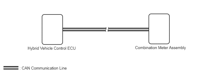
CAUTION / NOTICE / HINT
- NOTICE:
- ·
When replacing the combination meter assembly, always replace it with a new one. If a combination meter assembly which was installed to another vehicle is used, the information stored in it will not match the information from the vehicle and a DTC may be stored.
·When replacing any of the following ECUs, update the ECU security key.
-Combination meter assembly
-Hybrid vehicle control ECU
·Before replacing the hybrid vehicle control ECU, refer to Service Bulletin.
PROCEDURE
Check if CAN communication DTCs are output.
- Result:
Result Proceed to DTCs are not output A DTCs are output B
A
B
Check if hybrid control system DTCs are output.
- Powertrain > Hybrid Control > Trouble Codes
- 50001 397
- Result:
Result Proceed to DTCs are not output A DTCs are output B
A
B
for 2WD: Click hereEngine / Hybrid System>HYBRID / BATTERY CONTROL>HYBRID CONTROL SYSTEM (for 2WD)>DIAGNOSTIC TROUBLE CODE CHART202111,999999,_51,_111804,_0508963,RM10000000202R4,
for AWD: Click hereEngine / Hybrid System>HYBRID / BATTERY CONTROL>HYBRID CONTROL SYSTEM (for AWD)>DIAGNOSTIC TROUBLE CODE CHART202111,999999,_51,_111804,_0501632,RM100000001Z6WJ,
Perform the Active Test according to the display on the GTS.
- Body Electrical > Combination Meter > Active Test
-
Tester Display Measurement Item Control Range Diagnostic Note HV/EV System Indicator (MIN) Hybrid system indicator value
(Charge area lower limit)ON See [Display 1] HV/EV System Indicator (-50%) Hybrid system indicator value
(Charge area)ON See [Display 1] HV/EV System Indicator (0%) Hybrid system indicator value
(Charge area/eco area boundary)ON See [Display 1] HV/EV System Indicator (100%) Hybrid system indicator value
(Eco area/power area boundary)ON See [Display 1] HV/EV System Indicator (200%) Hybrid system indicator value
(Power area)ON See [Display 1] HV/EV System Indicator (300%) Hybrid system indicator value
(Power area)ON See [Display 1] HV/EV System Indicator (400%) Hybrid system indicator value
(Power area)ON See [Display 1] HV/EV System Indicator (MAX) Hybrid system indicator value
(Power area upper limit)ON See [Display 1]
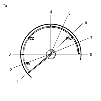
| *a | Hybrid System Indicator |
- HINT:
-
Refer to the following table for the specified hybrid system indicator position for each selected value:
Tester Display Hybrid System Indicator Indication HV/EV System Indicator
(MIN)Approximately 1 is indicated HV/EV System Indicator
(-50%)Approximately 2 is indicated HV/EV System Indicator
(0%)Approximately 3 is indicated HV/EV System Indicator
(100%)Approximately 4 is indicated HV/EV System Indicator
(200%)Approximately 5 is indicated HV/EV System Indicator
(300%)Approximately 6 is indicated HV/EV System Indicator
(400%)Approximately 7 is indicated HV/EV System Indicator
(MAX)Approximately 8 is indicated
- Body Electrical > Combination Meter > Active Test
-
Tester Display HV System Indicator (MIN) - 50004 409 256
- Body Electrical > Combination Meter > Active Test
-
Tester Display HV System Indicator (-50%) - 50004 409 257
- Body Electrical > Combination Meter > Active Test
-
Tester Display HV System Indicator (0%) - 50004 409 258
- Body Electrical > Combination Meter > Active Test
-
Tester Display HV System Indicator (100%) - 50004 409 259
- Body Electrical > Combination Meter > Active Test
-
Tester Display HV System Indicator (200%) - 50004 409 260
- Body Electrical > Combination Meter > Active Test
-
Tester Display HV System Indicator (300%) - 50004 409 261
- Body Electrical > Combination Meter > Active Test
-
Tester Display HV System Indicator (400%) - 50004 409 262
- Body Electrical > Combination Meter > Active Test
-
Tester Display HV System Indicator (MAX) - 50004 409 263
- Result:
Result Proceed to Active Test can be performed correctly A Active Test cannot be performed correctly B
A
B