BRAKE CONTROL / DYNAMIC CONTROL SYSTEMS ELECTRONICALLY CONTROLLED BRAKE SYSTEM(for Gasoline Model) C14D71C Multi-axis Acceleration Sensor Module "A" Supply Voltage Circuit Voltage Out of Range
DESCRIPTION
The airbag sensor assembly has a built-in yaw rate and acceleration sensor and detects the vehicle condition.
This DTC is stored when the skid control ECU (brake actuator assembly) receives a sensor supply voltage malfunction signal from the yaw rate and acceleration sensor (airbag sensor assembly).
| DTC No. | Detection Item | DTC Detection Condition | Trouble Area | DTC Output from | Priority |
|---|---|---|---|---|---|
| C14D71C | Multi-axis Acceleration Sensor Module "A" Supply Voltage Circuit Voltage Out of Range | Vehicle speed is 6 km/h (4 mph) or more and acceleration sensor (airbag sensor assembly) power supply malfunction signal is received for 1 second or more. | ·
Wire harness or connector ·
Acceleration sensor (airbag sensor assembly) |
Brake/EPB | A |
WIRING DIAGRAM
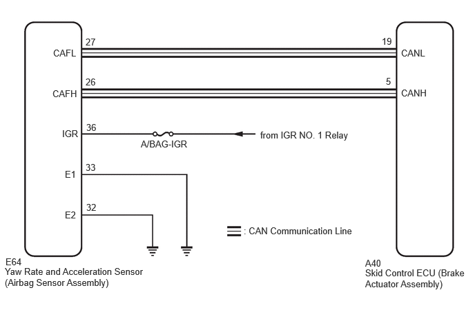
CAUTION / NOTICE / HINT
- NOTICE:
- ·
Inspect the fuses for circuits related to this system before performing the following procedure.
·When removing/installing a supplemental restraint systems related component, disconnect the cable from the negative (-) battery terminal before performing the procedure.
PROCEDURE
Pre-procedure1
Turn the ignition switch off.
Disconnect the cable from the negative (-) battery terminal.
- CAUTION:
-
Wait at least 60 seconds after disconnecting the cable from the negative (-) battery terminal to disable the SRS system.
Procedure1
Make sure that there is no looseness at the locking part and the connecting part of the connector.
- OK:
The connector is securely connected.
Pre-procedure2
Disconnect the E64 yaw rate and acceleration sensor (airbag sensor assembly) connector.
Procedure2
Check both the connector case and the terminals for deformation and corrosion.
- OK:
No deformation or corrosion.
Pre-procedure3
Connect the cable to the negative (-) battery terminal.
Turn the ignition switch to ON.
Operate all the components of the electrical system (defogger, wipers, headlights, heater blower, etc.).
Procedure3
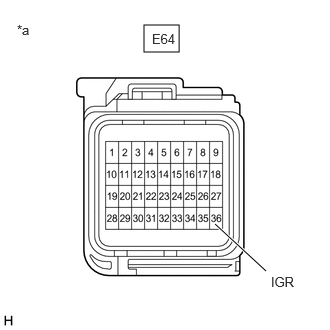
| *a | Front view of wire harness connector
(to Yaw Rate and Acceleration Sensor (Airbag Sensor Assembly)) |
Measure the voltage according to the value(s) in the table below.
- Standard Voltage:
Tester Connection Condition Specified Condition Click Location & Routing(E64)Location & Routingewd_type=routing;type=c;code=E64
Click Connector(E64)Instrument Panel>Instrument Panel Wire / Radio Wiring Sub-Assy / Telephone Computer Wire>Airbag Sensor Assemblyewd_type=component;type=c;code=E64;pinno=36
E64-36 (IGR) - Body ground Ignition switch ON 8 to 16 V
- Result:
Proceed to OK NG
Post-procedure1
None
OK
NG
Pre-procedure1
Turn the ignition switch off.
Disconnect the cable from the negative (-) battery terminal.
- CAUTION:
-
Wait at least 60 seconds after disconnecting the cable from the negative (-) battery terminal to disable the SRS system.
Procedure1
Make sure that there is no looseness at the locking part and the connecting part of the connector.
- OK:
The connector is securely connected.
Pre-procedure2
Disconnect the E64 yaw rate and acceleration sensor (airbag sensor assembly) connector.
Procedure2
Check both the connector case and the terminals for deformation and corrosion.
- OK:
No deformation or corrosion.
Procedure3
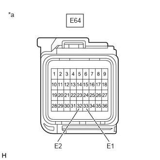
| *a | Front view of wire harness connector
(to Yaw Rate and Acceleration Sensor (Airbag Sensor Assembly)) |
Measure the resistance according to the value(s) in the table below.
- Standard Resistance:
Tester Connection Condition Specified Condition Click Location & Routing(E64)Location & Routingewd_type=routing;type=c;code=E64
Click Connector(E64)Instrument Panel>Instrument Panel Wire / Radio Wiring Sub-Assy / Telephone Computer Wire>Airbag Sensor Assemblyewd_type=component;type=c;code=E64;pinno=33,32
E64-33 (E1) - Body ground 1 minute or more after disconnecting the cable from the negative (-) battery terminal Below 1 Ω E64-32 (E2) - Body ground 1 minute or more after disconnecting the cable from the negative (-) battery terminal Below 1 Ω
- Result:
Proceed to OK NG
Post-procedure1
None
OK
NG