TELEMATICS TELEMATICS SYSTEM Emergency Call Switch Illumination Circuit
WIRING DIAGRAM
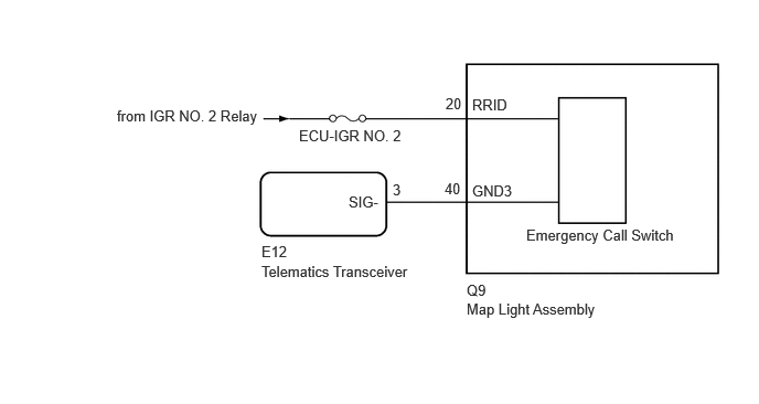
CAUTION / NOTICE / HINT
- NOTICE:
- ·
Depending on the parts that are replaced during vehicle inspection or maintenance, performing initialization, registration or calibration may be needed. Refer to Precaution for Telematics System.
·Before replacing the telematics transceiver, refer to Service Bulletin.
PROCEDURE
Disconnect the E12 telematics transceiver connector.
Disconnect the Q9 map light assembly connector.
Measure the resistance according to the value(s) in the table below.
- Standard Resistance:
Tester Connection Condition Specified Condition Click Location & Routing(E12,Q9)Location & Routingewd_type=routing;type=c,c;code=E12,Q9
Click Connector(E12)Instrument Panel>Instrument Panel Wire / Telephone Computer Wire>Telephone Transceiverewd_type=component;type=c;code=E12;pinno=3
Click Connector(Q9)Body>Roof Wire>Map Light Assemblyewd_type=component;type=c;code=Q9;pinno=40
E12-3 (SIG-) - Q9-40 (GND3) Always Below 1 Ω E12-3 (SIG-) or Q9-40 (GND3) - Body ground Always 10 kΩ or higher
Measure the voltage according to the value(s) in the table below.
- Standard Voltage:
Tester Connection Condition Specified Condition Click Location & Routing(Q9)Location & Routingewd_type=routing;type=c;code=Q9
Click Connector(Q9)Body>Roof Wire>Map Light Assemblyewd_type=component;type=c;code=Q9;pinno=20
Q9-20 (RRID) - Body Ground Ignition switch to ON 11 to 14 V
- Result:
Proceed to OK NG
OK
NG
Remove the map light assembly.
Connect 4 1.5 V dry-cell batteries in series.
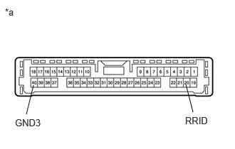
| *a | Component without harness connected
(Map Light Assembly) |
Connect a positive (+) lead from the batteries to terminal 20 (RRID), and a negative (-) lead to terminal 40 (GND3) of the map light assembly connector.
Check if the emergency call switch illumination comes on.
- OK:
The emergency call switch illumination comes on.
- Result:
Proceed to OK NG
OK
NG