AXLE AND DIFFERENTIAL STEERING KNUCKLE INSTALLATION
CAUTION / NOTICE / HINT
- NOTICE:
- ·
When removing or installing the front disc brake caliper assembly, pushing back the disc brake piston may cause a large clearance between the brake pads and brake disc. When the brake pedal is depressed with a large clearance between the brake pads and the brake disc, DTC C140000 and/or C140A00 related to abnormal brake fluid pressure may be stored. Make sure to clear any DTCs after performing this procedure. (for HV Model)
·While the auxiliary battery is connected, even if the ignition switch is off, the brake control system activates when the brake pedal is depressed or any door courtesy switch turns on. Therefore, when servicing the brake system components, do not operate the brake pedal or open/close the doors while the auxiliary battery is connected. (for HV Model)
- HINT:
- ·
Use the same procedure for the RH side and LH side.
·The following procedure is for the LH side.
PROCEDURE

 43212
1.INSTALL STEERING KNUCKLE
43212
1.INSTALL STEERING KNUCKLE
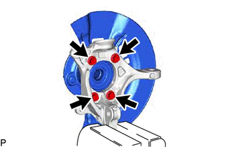
Secure the steering knuckle between aluminum plates in a vise.
- NOTICE:
-
Do not overtighten the vise.
Install the front axle hub sub-assembly and front disc brake dust cover to the steering knuckle with the 4 bolts.
- Torque:
- 120 N*m (1224 kgf*cm, 89 ft.*lbf)
- NOTICE:
- ·
Be careful not to damage the speed sensor rotor or contact surfaces.
·Do not allow foreign matter to contact the speed sensor rotor or contact surfaces.
43340A
2.INSTALL FRONT LOWER BALL JOINT ASSEMBLY
3.INSTALL FRONT AXLE ASSEMBLY