DOOR / HATCH POWER BACK DOOR DRIVE UNIT REMOVAL
CAUTION / NOTICE / HINT
The necessary procedures (adjustment, calibration, initialization, or registration) that must be performed after parts are removed and installed, or replaced during multiplex network power back door drive unit removal/installation are shown below.
| Replaced Part or Performed Procedure | Necessary Procedure | Effect/Inoperative Function when Necessary Procedure not Performed | Link |
|---|---|---|---|
·
Power back door unit assembly set LH* ·
Power back door unit assembly set RH* |
Reset back door close position | Power Back Door System | ( 202111,999999,_59,_111831,_0505274,RM100000001ZMEG,) 202111,999999,_59,_111831,_0505274,RM100000001ZMEG,)
|
- HINT:
- ·
Use the same procedure for the RH side and LH side.
·The following procedure is for the LH side.
PROCEDURE

 67939B
1.REMOVE BACK DOOR CENTER GARNISH
67939B
1.REMOVE BACK DOOR CENTER GARNISH
67938A
2.REMOVE BACK DOOR SIDE GARNISH LH
67937B
3.REMOVE BACK DOOR SIDE GARNISH RH
- HINT:
-
Use the same procedure as for the LH side.
64785A
4.REMOVE BACK DOOR TRIM BASE
74811D
5.REMOVE DOOR PULL HANDLE
67750
6.REMOVE BACK DOOR TRIM BOARD ASSEMBLY
68920
7.REMOVE POWER BACK DOOR UNIT SET ASSEMBLY
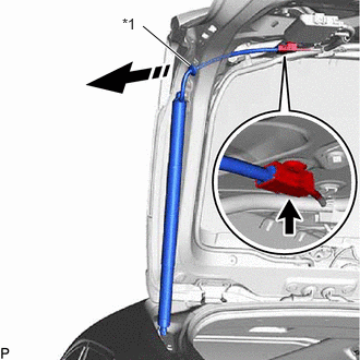
| *1 | Grommet |

|
Remove in this Direction |
Disconnect the connector.
Disengage the grommet as shown in the illustration.
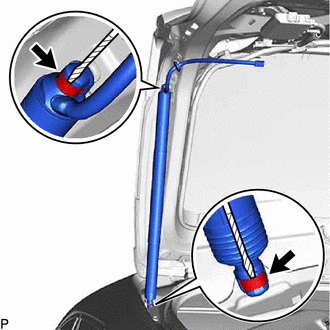

|
Protective Tape |
Using a screwdriver with its tip wrapped with protective tape, slightly raise the 2 stop rings as shown in the illustration.
Disengage the 2 ball joints to remove the power back door unit set assembly.
- NOTICE:
- ·
Remove the power back door unit set assembly while supporting the back door by hand.
·Make sure to replace the power back door unit set assembly with a new one.
68946
8.REMOVE BACK DOOR DAMPER STAY UPPER BRACKET
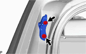
Remove the 2 bolts and back door damper stay upper bracket.
68948
9.REMOVE BACK DOOR DAMPER STAY LOWER BRACKET
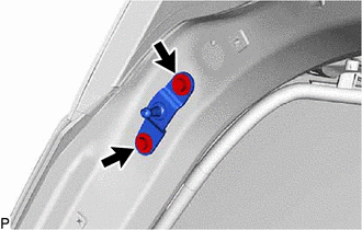
Remove the 2 bolts and back door damper stay lower bracket.