REAR SUSPENSION REAR STABILIZER BAR INSTALLATION
PROCEDURE

 48818
1.INSTALL REAR STABILIZER BUSHING
48818
1.INSTALL REAR STABILIZER BUSHING
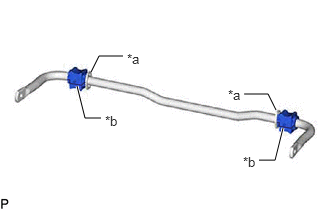
| *a | Stopper |
| *b | Cutout |
Install the 2 rear stabilizer bushings to the outside of the stoppers on the rear stabilizer bar.
- NOTICE:
-
Be sure to install the rear stabilizer bushings so that each cutout faces the front of the vehicle.
- HINT:
-
The cutout of the rear stabilizer bushing can be positioned either up or down.
48832A
2.INSTALL REAR NO. 1 STABILIZER BAR BRACKET
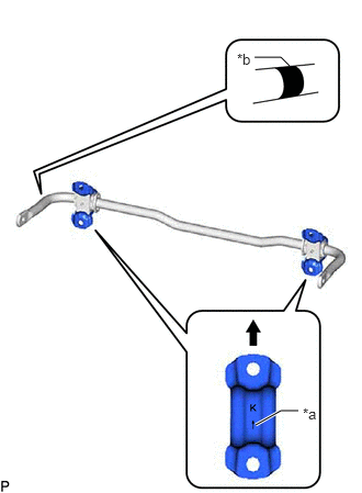
| *a | Arrow Mark |
| *b | Identification Mark |

|
Upper side of the Vehicle |
Install the 2 rear No. 1 stabilizer bar brackets to the 2 rear stabilizer bushings.
- NOTICE:
- ·
Ensure that the identification mark faces the right side of the vehicle.
·Be sure to install the rear No. 1 stabilizer bar bracket so that each arrow mark faces the upper side of the vehicle.
48835
3.INSTALL REAR LOWER STABILIZER BRACKET
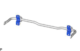
Install the 2 rear lower stabilizer brackets to the 2 rear stabilizer bushings.
48812
4.INSTALL REAR STABILIZER BAR

| *a | Identification Mark |
Install the rear stabilizer bar, 2 rear No. 1 stabilizer bar brackets, 2 rear lower stabilizer bar brackets and 2 rear stabilizer bushings to the rear suspension member sub-assembly with the 4 bolts.
- Torque:
- 78 N*m (795 kgf*cm, 58 ft.*lbf)
- NOTICE:
- ·
Ensure that the identification mark faces the right side of the vehicle.
·Temporarily tighten the bolt (A) and then fully tighten the 2 bolts in the order of (B) and (A).
5.STABILIZE SUSPENSION
48840A
6.INSTALL REAR STABILIZER LINK ASSEMBLY LH

| *a | Torque Wrench Fulcrum Length |
Using a ball joint lock nut wrench, install the rear stabilizer link assembly LH with the nut (A).
- Torque:
- 100 N*m (1020 kgf*cm, 74 ft.*lbf)
- HINT:
- ·
If the ball joint turns together with the nut, use a 6 mm hexagon socket wrench to hold the stud bolt.
·Calculate the torque wrench reading when changing the fulcrum length of the torque wrench.
·When using a ball joint lock nut wrench (fulcrum length of 149 mm (5.86 in.)) + torque wrench (fulcrum length of 400 cm (13.1 ft.)):
73 N*m (744 kgf*cm, 54 ft.*lbf)
Install the rear stabilizer link assembly LH with the bolt and nut (B).
- Torque:
- 81 N*m (826 kgf*cm, 60 ft.*lbf)
- NOTICE:
-
Because the nut has its own stopper, do not turn the nut. Tighten the bolt with the nut secured.
48830D
7.INSTALL REAR STABILIZER LINK ASSEMBLY RH
- HINT:
-
Perform the same procedure as for the LH side.
58327B
8.INSTALL MAIN MUFFLER HEAT INSULATOR
Install the main muffler heat insulator to the vehicle body with the 4 nuts.
- Torque:
- 4.9 N*m (50 kgf*cm, 43 in.*lbf)
17430
9.INSTALL TAIL EXHAUST PIPE ASSEMBLY
for M20C-FKS, M20D-FKS: Click hereEngine / Hybrid System>M20C-FKS, M20D-FKS (INTAKE / EXHAUST)>EXHAUST PIPE>INSTALLATION202111,202303,_51,_111792,_0503719,RM100000001ZFP7,202303,999999,_51,_111792,_0503719,RM1000000029Z2O,
for A25D-FXS, A25F-FXS: Click hereEngine / Hybrid System>A25D-FXS, A25F-FXS (INTAKE / EXHAUST)>EXHAUST PIPE>INSTALLATION202111,202303,_51,_111802,_0503724,RM100000001ZFPK,202303,999999,_51,_111802,_0503724,RM1000000029Z30,
10.INSTALL REAR WHEEL
11.INSPECT FOR EXHAUST GAS LEAK
for M20C-FKS, M20D-FKS: Click hereEngine / Hybrid System>M20C-FKS, M20D-FKS (INTAKE / EXHAUST)>EXHAUST PIPE>INSTALLATION202111,202303,_51,_111792,_0503719,RM100000001ZFP7_01_0041,202303,999999,_51,_111792,_0503719,RM1000000029Z2O_01_0041,
for A25D-FXS, A25F-FXS: Click hereEngine / Hybrid System>A25D-FXS, A25F-FXS (INTAKE / EXHAUST)>EXHAUST PIPE>INSTALLATION202111,202303,_51,_111802,_0503724,RM100000001ZFPK_01_0041,202303,999999,_51,_111802,_0503724,RM1000000029Z30_01_0041,