POWER ASSIST SYSTEMS POWER STEERING SYSTEM EPS Warning Light Circuit
DESCRIPTION
Perform the following troubleshooting procedure when the EPS warning light remains on after the ignition switch is turned to ON (READY) but no DTCs are stored.
Perform the following troubleshooting procedure when the EPS warning light remains on after the engine is started, but no DTCs are stored.
- HINT:
- ·
If the power steering ECU (rack and pinion power steering gear assembly) detects a malfunction in the power source voltage input (IG) circuit, the EPS warning light illuminates.
·If the power steering ECU (rack and pinion power steering gear assembly) detects a drop in the power voltage input (IG and PIG) circuit, the force required to turn the steering wheel may increase, the EPS warning light turns on in order to warn the driver.
WIRING DIAGRAM
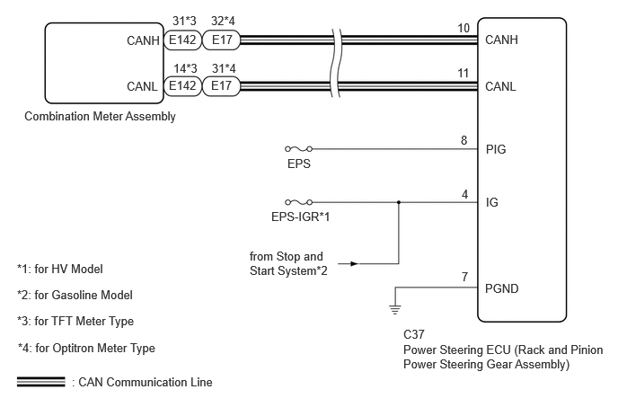
CAUTION / NOTICE / HINT
- NOTICE:
- ·
Inspect the fuses for circuits related to this system before performing the following procedure.
PROCEDURE
Check the vehicle control history (RoB).
- HINT:
-
If vehicle control history (RoB) is stored, the EPS warning light may illuminate.
- Result:
Result Proceed to Vehicle control history (RoB) of power steering system control does not exist A Vehicle control history (RoB) of power steering system control exists B
A
B
- NOTICE:
-
After performing inspections and repairs on the system related to the vehicle control history (RoB), clear the vehicle control history (RoB).
Jiggle the rack and pinion power steering gear assembly connectors and wire harness up and down, and left and right to check the illumination condition of the EPS warning light in the combination meter assembly.
- OK:
The EPS warning light illumination condition does not change.
- HINT:
- for HV Model:
When the EPS warning light is operating properly, it illuminates when the ignition switch is turned to ON and turns off when the ignition switch is ON (READY).
- for Gasoline Model:
When the EPS warning light is operating properly, it illuminates when the ignition switch is turned to ON and turns off when the engine is started.
- Result:
Proceed to OK NG
OK
NG
Disconnect the C37 rack and pinion power steering gear assembly connector.
Measure the voltage according to the value(s) in the table below.
- Standard Voltage:
Tester Connection Condition Specified Condition Click Location & Routing(C37)Location & Routingewd_type=routing;type=c;code=C37
Click Connector(C37)Engine Compartment>Engine Wire>Power Steering ECU with Motor Assembly (Rack and Pinion Power Steering Gear Assembly)ewd_type=component;type=c;code=C37;pinno=4,8
C37-4 (IG) - Body ground Ignition switch ON 11 to 14 V C37-8 (PIG) - Body ground Ignition switch ON 11 to 14 V
Measure the resistance according to the value(s) in the table below.
- Standard Resistance:
Tester Connection Condition Specified Condition Click Location & Routing(C37)Location & Routingewd_type=routing;type=c;code=C37
Click Connector(C37)Engine Compartment>Engine Wire>Power Steering ECU with Motor Assembly (Rack and Pinion Power Steering Gear Assembly)ewd_type=component;type=c;code=C37;pinno=7
C37-7 (PGND) - Body ground Always Below 1 Ω
- Result:
Proceed to OK NG
OK
NG
Check the combination meter assembly.
for Optitron Meter Type: Click hereVehicle Interior>METER / GAUGE / DISPLAY>METER / GAUGE SYSTEM (for Optitron Meter Type)>HOW TO PROCEED WITH TROUBLESHOOTING202111,999999,_58,_111835,_0504957,RM100000001ZKLL,
for TFT Meter Type: Click hereVehicle Interior>METER / GAUGE / DISPLAY>METER / GAUGE SYSTEM (for TFT Meter Type)>HOW TO PROCEED WITH TROUBLESHOOTING202111,999999,_58,_111835,_0504958,RM100000001ZKMB,
- Result:
Proceed to OK NG
OK
NG
for Optitron Meter Type: Click hereVehicle Interior>METER / GAUGE / DISPLAY>METER / GAUGE SYSTEM (for Optitron Meter Type)>HOW TO PROCEED WITH TROUBLESHOOTING202111,999999,_58,_111835,_0504957,RM100000001ZKLL,
for TFT Meter Type: Click hereVehicle Interior>METER / GAUGE / DISPLAY>METER / GAUGE SYSTEM (for TFT Meter Type)>HOW TO PROCEED WITH TROUBLESHOOTING202111,999999,_58,_111835,_0504958,RM100000001ZKMB,