RM38N0EC
_55
Steering
_111819
POWER ASSIST SYSTEMS
_0501137
POWER STEERING SYSTEM
C
POWER ASSIST SYSTEMS POWER STEERING SYSTEM C123A17 Supply Voltage Circuit Circuit Voltage Above Threshold
DESCRIPTION
| DTC No. | Detection Item | DTC Detection Condition | Trouble Area | Warning Indicate | DTC Output from | Priority |
|---|---|---|---|---|---|---|
| C123A17 | Supply Voltage Circuit Circuit Voltage Above Threshold | IG voltage is higher than the standard value | ·
Harness or connector ·
Rack and pinion power steering gear assembly |
EPS warning light: Comes on | EMPS | A |
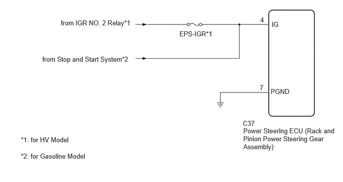
WIRING DIAGRAM
1.271,0.396 2.823,0.771
1.552,0.375
10
false
from IGR NO. 2 Relay*1
3.75,0.625 4.542,0.875
0.792,0.25
10
false
EPS-IGR*1
5.438,0.333 6.052,0.552
0.615,0.219
10
false
4
5.677,0.427 6.292,0.646
0.615,0.219
10
false
IG
5.656,1.833 6.271,2.052
0.615,0.219
10
false
PGND
5.427,1.75 6.042,1.969
0.615,0.219
10
false
7
5.073,2.5 5.771,2.719
0.698,0.219
10
false
C37
5.083,2.656 7.073,3.208
1.99,0.552
10
false
Power Steering ECU (Rack and Pinion Power Steering Gear Assembly)
0.885,1.156 2.865,1.406
1.979,0.25
10
false
from Stop and Start System*2
0.438,2.844 2.885,3.042
2.448,0.198
10
false
*1: for HV Model
0.438,3.188 3.802,3.385
3.365,0.198
10
false
*2: for Gasoline Model
CAUTION / NOTICE / HINT
- NOTICE:
- ·
Inspect the fuses for circuits related to this system before performing the following procedure.
PROCEDURE
1.CHECK HARNESS AND CONNECTOR (IG POWER SOURCE)
Pre-procedure1
a.
Disconnect the C37 rack and pinion power steering gear assembly connector.
Procedure1
b.
Measure the voltage according to the value(s) in the table below.
- Standard Voltage:
Tester Connection Condition Specified Condition Click Location & Routing(C37)Location & Routingewd_type=routing;type=c;code=C37
Click Connector(C37)Engine Compartment>Engine Wire>Power Steering ECU with Motor Assembly (Rack and Pinion Power Steering Gear Assembly)ewd_type=component;type=c;code=C37;pinno=4
C37-4 (IG) - Body ground Ignition switch ON 11 to 14 V
- Result:
Proceed to OK NG
Post-procedure1
c.
None
OK
2.CLEAR DTC
NG
REPAIR OR REPLACE HARNESS OR CONNECTOR
2.CLEAR DTC
Pre-procedure1
a.
None
Procedure1
b.
Clear the DTCs.
- Chassis > EMPS > Clear DTCs
- 50002 405
- Result:
Proceed to NEXT
Post-procedure1
c.
Turn the ignition switch off.
NEXT
3.CHECK FOR DTC
3.CHECK FOR DTC
a.
Check for DTCs.
- Chassis > EMPS > Trouble Codes
- 50001 405
- Result:
Result Proceed to C123A17 is output A DTCs are not output B
A
REPLACE RACK AND PINION POWER STEERING GEAR ASSEMBLY
B
USE SIMULATION METHOD TO CHECK