BRAKE CONTROL / DYNAMIC CONTROL SYSTEMS BRAKE PEDAL STROKE SENSOR INSTALLATION
PROCEDURE

 1.INSPECT AND ADJUST BRAKE PEDAL HEIGHT
89510D
2.INSTALL BRAKE PEDAL STROKE SENSOR ASSEMBLY
- NOTICE:
- ·
Do not drop the brake pedal stroke sensor assembly.
·If the brake pedal stroke sensor assembly has been dropped, replace the brake pedal stroke sensor assembly with a new one.
When installing a new brake pedal stroke sensor assembly:
- NOTICE:
-
Do not break the brake pedal stroke sensor assembly lever set pin before installing the brake pedal stroke sensor assembly with the 2 nuts.
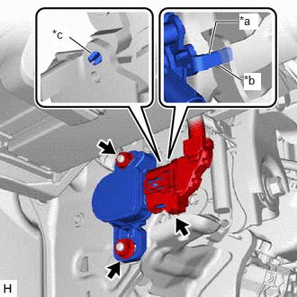
| *a | Brake Pedal Stroke Sensor Assembly Lever |
| *b | Brake Pedal Groove |
| *c | Brake Pedal Stroke Sensor Assembly Lever Set Pin |
Install a new brake pedal stroke sensor assembly to the brake pedal support assembly with the 2 nuts.
- Torque:
- 8.5 N*m (87 kgf*cm, 75 in.*lbf)
- NOTICE:
- ·
Engage the brake pedal stroke sensor assembly lever with the brake pedal groove.
·Check that there is no foreign matter attached to the contact surface of the brake pedal stroke sensor assembly.
·Check that the tip of the brake pedal stroke sensor assembly lever is protruding from the brake pedal groove.
Connect the connector.
Firmly depress the brake pedal to break the brake pedal stroke sensor assembly lever set pin.
Remove the broken lever set pin.
When reusing the brake pedal stroke sensor assembly:

| *a | Brake Pedal Stroke Sensor Assembly Lever |
| *b | Brake Pedal Groove |
Install the brake pedal stroke sensor assembly to the brake pedal support assembly and temporarily tighten the 2 nuts.
- NOTICE:
- ·
Engage the brake pedal stroke sensor assembly lever with the brake pedal groove.
·Check that there is no foreign matter attached to the contact surface of the brake pedal stroke sensor assembly.
·Check that the tip of the brake pedal stroke sensor assembly lever is protruding from the brake pedal groove.
- HINT:
-
The nut will be fully tightened when adjusting the brake pedal stroke sensor assembly.
Connect the connector.
3.CONNECT CABLE TO NEGATIVE AUXILIARY BATTERY TERMINAL
89510D
4.ADJUST BRAKE PEDAL STROKE SENSOR ASSEMBLY
- NOTICE:
- ·
When the brake pedal stroke sensor assembly is being reused, perform the following procedure to adjust it.
·Do not depress the brake pedal after turning the ignition switch to ON.
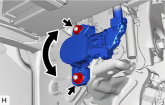
Read the stroke sensor value in the Data List, and turn the brake pedal stroke sensor assembly slowly to the right or left to adjust the output voltage so that it is within the following range.
- Chassis > Brake Booster > Data List
-
Tester Display Stroke Sensor - 50003 466 207
- Standard Voltage (without the brake pedal depressed):
0.8 to 1.2 V
Fully tighten the 2 nuts.
- Torque:
- 8.5 N*m (87 kgf*cm, 75 in.*lbf)
55606
5.INSTALL NO. 1 INSTRUMENT PANEL UNDER COVER SUB-ASSEMBLY
62112A
6.INSTALL COWL SIDE TRIM SUB-ASSEMBLY LH
67914B
7.INSTALL FRONT DOOR SCUFF PLATE LH
8.PERFORM INITIALIZATION AND CALIBRATION
9. CHECK AND CLEAR DTC