PARK ASSIST / MONITORING REAR VIEW MONITOR SYSTEM TERMINALS OF ECU
REAR TELEVISION CAMERA ASSEMBLY
Disconnect the T19 rear television camera assembly connector.

Measure the voltage of each terminal of the wire harness side connector.
| Terminal No. (Symbol) | Terminal Description | Condition | Specified Condition |
|---|---|---|---|
| T19-6 (CB+) - Body ground | Power source | Ignition switch ACC | 5.5 to 7.05 V |
If the result is not as specified, there may be a malfunction on the wire harness side.
Reconnect the T19 rear television camera assembly connector.
Measure the voltage and check for pulses at each terminal of the connector.
| Terminal No. (Symbol) | Terminal Description | Condition | Specified Condition |
|---|---|---|---|
| T19-3 (CV+) - T19-2 (CV-) | Video signal | Ignition switch ON
Reverse (R) selected Camera lens not covered, displaying an image |
Pulse generation
(Refer to waveform 1) |
| Ignition switch ON
Reverse (R) selected Camera lens covered, blacking out the screen |
Pulse generation
(Refer to waveform 2) |
||
| T19-5 (CGND) - Body ground | Shield ground | Always | Below 1 V |
- HINT:
-
A waterproof connector is used for the rear television camera assembly. Therefore, inspect the waveform at the radio and display receiver assembly with the connector connected.
If the result is not as specified, the rear television camera assembly may be malfunctioning.
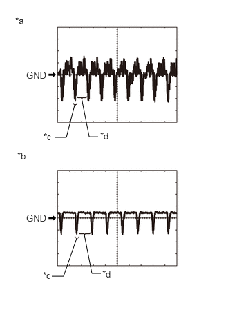
| *a | Waveform 1 (camera lens is not covered, displaying an image) |
| *b | Waveform 2 (camera lens is covered, blacking out the screen) |
| *c | Synchronization Signal |
| *d | Video Waveform |
Reference (Oscilloscope waveform):
- HINT:
-
A waterproof connector is used for the rear television camera assembly. Therefore, inspect the waveform at the radio and display receiver assembly with the connector connected.
Waveform 1 (camera lens is not covered, displaying an image)
| Item | Content |
|---|---|
| Measurement terminal | T19-3 (CV+) - T19-2 (CV-) |
| Measurement setting | 200 mV/DIV., 50 μs./DIV. |
| Condition | Ignition switch ON, reverse (R) selected |
- HINT:
- ·
The video waveform changes according to the image sent by the rear television camera assembly.
·The video waveform is constantly output when the ignition switch is ACC.
·Make sure that the rear camera is enabled in general settings.
Waveform 2 (camera lens is covered, blacking out the screen)
| Item | Content |
|---|---|
| Measurement terminal | T19-3 (CV+) - T19-2 (CV-) |
| Measurement setting | 200 mV/DIV., 50 μs./DIV. |
| Condition | Ignition switch ON, reverse (R) selected |
- HINT:
- ·
The video waveform changes according to the image sent by the rear television camera assembly.
·The video waveform is constantly output when the ignition switch is ACC.
·Make sure that the rear camera is enabled in general settings.
RADIO AND DISPLAY RECEIVER ASSEMBLY