HEATING / AIR CONDITIONING AIR CONDITIONING SYSTEM(for Gasoline Model) B14B97F Ion Generator Actuator Stuck Off
DESCRIPTION
The ion generator sub-assembly operates when the blower switch is on.
The air conditioning amplifier assembly sends a drive signal to the ion generator sub-assembly.
| DTC No. | Detection Item | DTC Detection Condition | Trouble Area | Memory | DTC Output from | Priority |
|---|---|---|---|---|---|---|
| B14B97F | Ion Generator Actuator Stuck Off | Diagnosis Condition:
Ignition switch is ON and blower switch is on Malfunction: Open or short in ion generator circuit Detection Time: Continuously for 12 seconds or more |
·
Ion generator sub-assembly ·
Harness or connector ·
Air conditioning amplifier assembly |
Memorized | Air Conditioner | A |
WIRING DIAGRAM
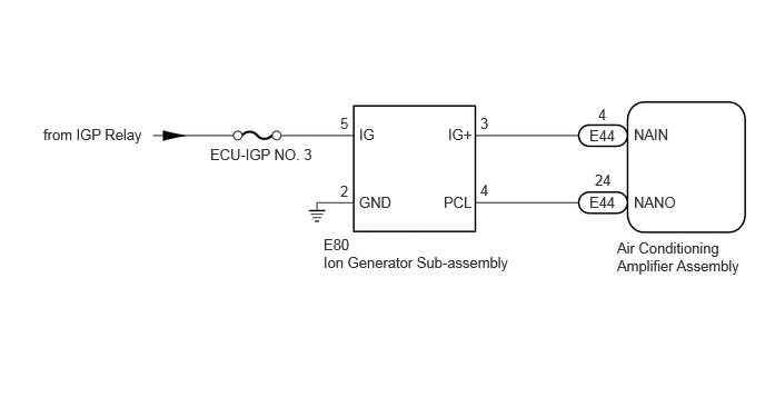
CAUTION / NOTICE / HINT
- NOTICE:
-
Inspect the fuses for circuits related to this system before performing the following procedure.
PROCEDURE
Perform the Active Test according to the display on the GTS.
- Body Electrical > Air Conditioner > Active Test
-
Tester Display Measurement Item Control Range Diagnostic Note Ion Generator This test activates the Ion Generator. OFF / ON Operate with ignition switch ON.
- Body Electrical > Air Conditioner > Active Test
-
Tester Display Ion Generator - 50004 450 14
- OK:
Ion generator sub-assembly operates normally.
- Result:
Proceed to OK NG
OK
NG
Pre-procedure1
Disconnect the E80 ion generator sub-assembly connector.
Procedure1
Measure the voltage according to the value(s) in the table below.
- Standard Voltage:
Tester Connection Condition Specified Condition Click Location & Routing(E80)Location & Routingewd_type=routing;type=c;code=E80
Click Connector(E80)Instrument Panel>Instrument Panel Wire / Radio Wiring Sub-Assy / Telephone Computer Wire>Ion Generator Sub-Assemblyewd_type=component;type=c;code=E80;pinno=5
E80-5 (IG) - Body ground Ignition switch ON 11 to 14 V
- Result:
Proceed to OK NG
Post-procedure1
None
OK
NG
Pre-procedure1
Disconnect the E80 ion generator sub-assembly connector.
Procedure1
Measure the resistance according to the value(s) in the table below.
- Standard Resistance:
Tester Connection Condition Specified Condition Click Location & Routing(E80)Location & Routingewd_type=routing;type=c;code=E80
Click Connector(E80)Instrument Panel>Instrument Panel Wire / Radio Wiring Sub-Assy / Telephone Computer Wire>Ion Generator Sub-Assemblyewd_type=component;type=c;code=E80;pinno=2
E80-2 (GND) - Body ground Always Below 1 Ω
- Result:
Proceed to OK NG
Post-procedure1
None
OK
NG
Pre-procedure1
Disconnect the E80 ion generator sub-assembly connector.
Disconnect the E44 air conditioning amplifier assembly connector.
Procedure1
Measure the resistance according to the value(s) in the table below.
- Standard Resistance:
Tester Connection Condition Specified Condition Click Location & Routing(E80,E44)Location & Routingewd_type=routing;type=c,c;code=E80,E44
Click Connector(E80)Instrument Panel>Instrument Panel Wire / Radio Wiring Sub-Assy / Telephone Computer Wire>Ion Generator Sub-Assemblyewd_type=component;type=c;code=E80;pinno=3,4
Click Connector(E44)Instrument Panel>Instrument Panel Wire / Radio Wiring Sub-Assy / Telephone Computer Wire>Air Conditioning Amplifier Assemblyewd_type=component;type=c;code=E44;pinno=4,24
E80-3 (IG+) - E44-4 (NAIN) Always Below 1 Ω E80-4 (PCL) - E44-24 (NANO) Always Below 1 Ω E80-3 (IG+) or E44-4 (NAIN) - Other terminals and body ground Always 10 kΩ or higher E80-4 (PCL) or E44-24 (NANO) - Other terminals and body ground Always 10 kΩ or higher
- Result:
Proceed to OK NG
Post-procedure1
None
OK
NG
Pre-procedure1
Disconnect the E80 ion generator sub-assembly connector.
Reconnect the E44 air conditioning amplifier assembly connector.
Procedure1
Measure the voltage according to the value(s) in the table below.
- Standard Voltage:
Tester Connection Condition Specified Condition Click Location & Routing(E80)Location & Routingewd_type=routing;type=c;code=E80
Click Connector(E80)Instrument Panel>Instrument Panel Wire / Radio Wiring Sub-Assy / Telephone Computer Wire>Ion Generator Sub-Assemblyewd_type=component;type=c;code=E80;pinno=3
E80-3 (IG+) - Body ground ·Ignition switch ON
·Blower switch: off
4.75 to 5.25 V
- Result:
Proceed to OK NG
Post-procedure1
None
OK
NG
Pre-procedure1
Connect the E80 ion generator sub-assembly connector.
Procedure1
Measure the voltage according to the value(s) in the table below.
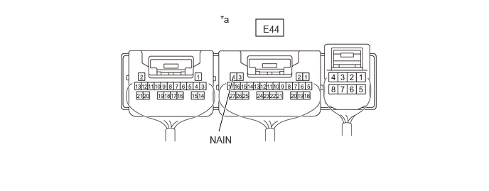
| *a | Component with harness connected
(Air Conditioning Amplifier Assembly) |
- | - |
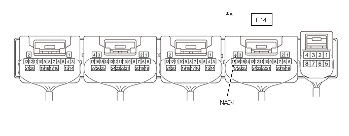
| *a | Component with harness connected
(Air Conditioning Amplifier Assembly) |
- | - |
- Standard Voltage:
Tester Connection Condition Specified Condition Click Location & Routing(E44)Location & Routingewd_type=routing;type=c;code=E44
Click Connector(E44)Instrument Panel>Instrument Panel Wire / Radio Wiring Sub-Assy / Telephone Computer Wire>Air Conditioning Amplifier Assemblyewd_type=component;type=c;code=E44;pinno=4
E44-4 (NAIN) - Body ground ·Ignition switch ON
·Blower switch: ON
Below 2.2 V
- Result:
Proceed to OK NG
Post-procedure1
None
OK
NG