M20C-FKS, M20D-FKS ENGINE MECHANICAL CAMSHAFT INSTALLATION
CAUTION / NOTICE / HINT
- NOTICE:
-
This procedure includes the installation of small-head bolts. Refer to Small-Head Bolts of Basic Repair Hint to identify the small-head bolts.
PROCEDURE

 1.INSTALL CAMSHAFT
- HINT:
-
Perform "Inspection After Repair" after replacing the intake camshaft sub-assembly, exhaust camshaft sub-assembly, camshaft timing gear assembly and camshaft timing exhaust gear assembly.

| *a | "0" Timing Mark |
| *b | Timing Mark |
Turn the crankshaft clockwise to align the timing mark (cutout) on the crankshaft pulley assembly with the "0" timing mark on the No. 2 timing chain cover assembly.
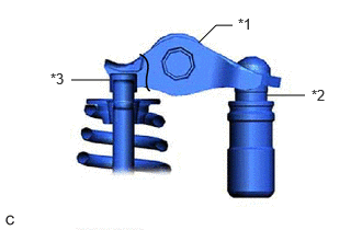
| *1 | No. 1 Valve Rocker Arm Sub-assembly |
| *2 | Valve Lash Adjuster Assembly |
| *3 | Valve Stem Cap |
Check that the No. 1 valve rocker arm sub-assembly is correctly installed as shown in the illustration.
Clean the camshaft housing sub-assembly and the cams and journals of the intake camshaft sub-assembly and exhaust camshaft sub-assembly, and then apply engine oil to them.
Apply a light coat of engine oil to the journals of the intake camshaft sub-assembly and install the intake camshaft sub-assembly to the camshaft housing sub-assembly.
Apply a light coat of engine oil to the journals of the exhaust camshaft sub-assembly and install the exhaust camshaft sub-assembly to the camshaft housing sub-assembly.
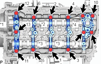
| *1 | No. 1 Camshaft Bearing Cap |
| *2 | No. 2 Camshaft Bearing Cap |
| *3 | No. 3 Camshaft Bearing Cap |
| *4 | No. 4 Camshaft Bearing Cap |
Set the No. 1 camshaft bearing cap, No. 2 camshaft bearing cap, 2 No. 3 camshaft bearing caps and No. 4 camshaft bearing cap as shown in the illustration.
Uniformly tighten the 13 bolts in the order shown in the illustration.
- Torque:
- 28.5 N*m (291 kgf*cm, 21 ft.*lbf)
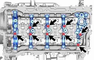
Uniformly tighten the 9 bolts in the order shown in the illustration.
- Torque:
- 16 N*m (163 kgf*cm, 12 ft.*lbf)
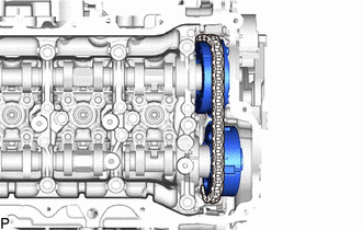
Set the camshaft timing gear assembly and camshaft timing exhaust gear assembly to the chain sub-assembly as shown in the illustration.
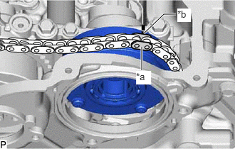
| *a | Paint Mark |
| *b | Timing Mark |
Align the timing mark on the camshaft timing gear assembly with the paint mark on the chain sub-assembly.
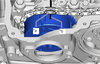
| *a | Paint Mark |
| *b | Timing Mark |
Align the timing mark on the camshaft timing exhaust gear assembly with the paint mark on the chain sub-assembly.
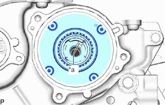
| *a | Knock Pin |
Using the hexagonal portion of the intake camshaft sub-assembly, install the camshaft timing gear assembly to the intake camshaft sub-assembly.
- NOTICE:
-
Do not damage the camshaft housing sub-assembly, cylinder head sub-assembly and spark plug tube.
Check that the knock pin matches the pin hole from the No. 2 timing chain cover assembly side.
Using a 10 mm bi-hexagon socket wrench, temporarily install the camshaft timing gear assembly with the bolt.
- HINT:
-
Temporarily install the bolt enough that the camshaft timing gear assembly does not detach from the knock pin of the intake camshaft sub-assembly.
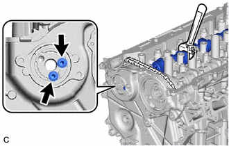
Using the hexagonal portion of the exhaust camshaft sub-assembly, install the camshaft timing exhaust gear assembly to the exhaust camshaft sub-assembly.
- NOTICE:
-
Do not damage the camshaft housing sub-assembly, cylinder head sub-assembly and spark plug tube.
Temporarily install the 2 bolts.
- HINT:
-
The 2 bolts can only be installed as shown in the illustration if the knock pin on the exhaust camshaft sub-assembly and the pin hole on the camshaft timing exhaust gear assembly match. If the 2 bolts cannot be installed, the knock pin and pin hole do not match.
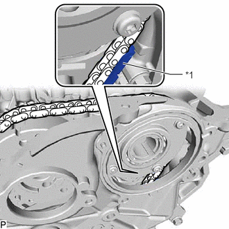
| *1 | No. 1 Chain Vibration Damper |
Check the status of the camshaft timing gear assembly and camshaft timing exhaust gear assembly temporarily installed to each camshaft.
Camshaft timing gear assembly side:
Check that the chain sub-assembly does not overlap the No. 1 chain vibration damper as shown in the illustration.
- NOTICE:
-
If the chain sub-assembly overlaps the No. 1 chain vibration damper, install it again.
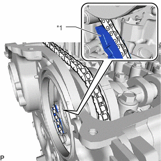
| *1 | Chain Tensioner Slipper |
Camshaft timing exhaust gear assembly side:
Check that the chain sub-assembly does not overlap the chain tensioner slipper as shown in the illustration.
- NOTICE:
-
If the chain sub-assembly overlaps the chain tensioner slipper, install it again.
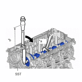
| *a | Hold |
| *b | Torque Wrench Fulcrum Length |

|
Turn |
Using the hexagonal portion of the intake camshaft sub-assembly, hold the intake camshaft sub-assembly.
- NOTICE:
- ·
Do not damage the camshaft housing sub-assembly, cylinder head sub-assembly and spark plug tube.
·Do not disassemble the camshaft timing gear assembly.
Using a 10 mm bi-hexagon socket wrench, tighten the bolt on the camshaft timing gear assembly.
- SST
- 09961-01270
- Torque:
- Specified tightening torque : 86 N*m (877 kgf*cm, 63 ft.*lbf)
- HINT:
- ·
Calculate the torque wrench reading when changing the fulcrum length of the torque wrench.
·When using SST (fulcrum length of 200 mm (7.87 in.)) + torque wrench (fulcrum length of 255 mm (10 in.)): 48 N*m (489 kgf*cm, 35 ft.*lbf)
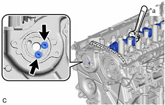
| *a | Hold |
Using the hexagonal portion of the exhaust camshaft sub-assembly, hold the exhaust camshaft sub-assembly.
- NOTICE:
-
Do not damage the camshaft housing sub-assembly, cylinder head sub-assembly and spark plug tube.
Using a 5 mm hexagon socket wrench, tighten the 2 bolts.
- Torque:
- 19 N*m (194 kgf*cm, 14 ft.*lbf)
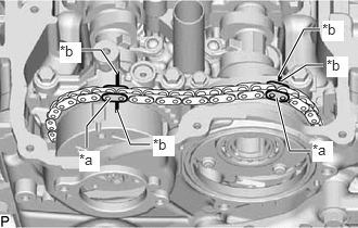
| *a | Paint Mark |
| *b | Timing Mark |
Check that the paint marks and timing marks are positioned as shown in the illustration.
Using the hexagonal portion of the intake camshaft sub-assembly, check that the chain sub-assembly slackens when the intake camshaft sub-assembly is moved in the direction shown in the illustration.
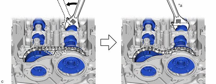
| *a | Hold | - | - |
|
|
Turn | - | - |
- NOTICE:
-
If the chain sub-assembly remains tight and does not slacken, the chain tensioner slipper and No. 1 chain vibration damper may overlap the chain sub-assembly, so install them again.
Remove the pin from the No. 1 chain tensioner assembly.
2.INSTALL STRAIGHT SCREW PLUG
3.SET NO. 1 CYLINDER TO TDC (COMPRESSION)
23477
4.INSTALL FUEL PUMP LIFTER GUIDE
11193
5.INSTALL SPARK PLUG TUBE GASKET
11201
6.INSTALL CYLINDER HEAD COVER SUB-ASSEMBLY
13090E
7.INSTALL CAM TIMING CONTROL MOTOR O-RING
13090D
8.INSTALL CAM TIMING CONTROL MOTOR WITH EDU ASSEMBLY
82286A
9.INSTALL NO. 2 EARTH WIRE
135A0B
10.INSTALL CAMSHAFT TIMING VALVE ASSEMBLY
11.INSTALL O-RING
15370
12.INSTALL CAM TIMING OIL CONTROL SOLENOID ASSEMBLY
19500
13.INSTALL IGNITION COIL ASSEMBLY
29300
14.INSTALL VACUUM PUMP ASSEMBLY
for M20 Series Engine, BOSCH Made:
for M20 Series Engine, except BOSCH Made:
23100X
15.INSTALL FUEL (ENGINE ROOM SIDE) PUMP ASSEMBLY (for High Pressure)