PARK ASSIST / MONITORING ULTRASONIC SENSOR(for Front) REMOVAL
CAUTION / NOTICE / HINT
The necessary procedures (adjustment, calibration, initialization or registration) that must be performed after parts are removed and installed, or replaced during ultrasonic sensor (for Front) removal/installation are shown below.
| Replaced Part or Performed Procedures | Necessary Procedures | Effect/Inoperative Function When Necessary Procedures are not Performed | Link |
|---|---|---|---|
| Front bumper assembly (Including removal and installation) | Front television camera view adjustment | Panoramic view monitor system | ( 202304,999999,_56,_083082,_0586733,RM1000000029R9F,) 202304,999999,_56,_083082,_0586733,RM1000000029R9F,)
|
·
Front television camera assembly, radiator grille assembly or front bumper assembly ·
Rear television camera assembly ·
Side television camera assembly LH or outer rear view mirror assembly LH ·
Side television camera assembly RH or outer rear view mirror assembly RH |
Television camera view adjustment (Adjustment of all cameras)
|
Panoramic view monitor system |
| Replaced Part or Performed Procedures | Necessary Procedures | Effect/Inoperative Function When Necessary Procedures are not Performed | Link |
|---|---|---|---|
| Front bumper assembly (Including removal and installation) | Front television camera view adjustment | Panoramic view monitor system | (202304,999999,_56,_083082,_0586733,RM1000000029R9F,)
|
·
Front television camera assembly, radiator grille assembly or front bumper assembly ·
Rear television camera assembly ·
Side television camera assembly LH or outer rear view mirror assembly LH ·
Side television camera assembly RH or outer rear view mirror assembly RH |
Television camera view adjustment (Adjustment of all cameras)
|
Panoramic view monitor system |
- HINT:
- ·
Use the same procedure for the RH and LH side.
·The following procedure is for the LH side.
PROCEDURE

 1.REMOVE FRONT BUMPER ASSEMBLY
89341K
2.REMOVE FRONT CORNER ULTRASONIC SENSOR
- NOTICE:
-
Before removing the sensor, make sure to mark the sensor and front bumper cover so that each sensor can be returned to its original position.
Detach the claw and remove the front corner ultrasonic sensor as shown in the illustration.

| *A | for Type A | *B | for Type B |
| *C | for Off Road Package | - | - |

|
Remove in this Direction | - | - |
Disconnect the connector.
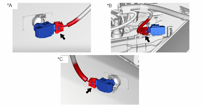
| *A | for Type A | *B | for Type B |
| *C | for Off Road Package | - | - |
89341L
3.REMOVE FRONT CENTER ULTRASONIC SENSOR
- NOTICE:
-
Before removing the sensor, make sure to mark the sensor and front bumper cover so that each sensor can be returned to its original position.
Detach the claw and remove the front center ultrasonic sensor as shown in the illustration.
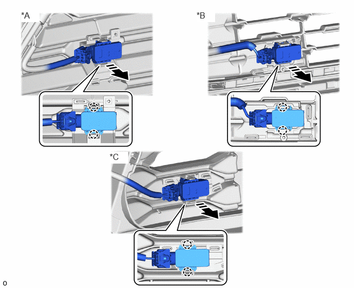
| *A | for Type A | *B | for Type B |
| *C | for Off Road Package | - | - |
|
|
Remove in this Direction | - | - |
Disconnect the connector.
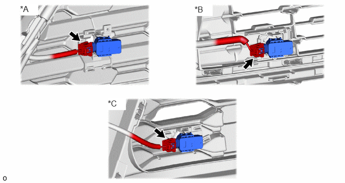
| *A | for Type A | *B | for Type B |
| *C | for Off Road Package | - | - |
89C48D
4.REMOVE FRONT CORNER ULTRASONIC SENSOR RETAINER (for Type A, for Off Road Package)
- HINT:
- ·
Perform the following procedure only when replacement of a front corner ultrasonic sensor retainer is necessary.
·When removing the front corner ultrasonic sensor retainer, if the double-sided tape is difficult to remove, heat the adhesive of the front corner ultrasonic sensor retainer and front bumper assembly using a heat light.
Heat the front bumper assembly and front corner ultrasonic sensor retainer using a heat light.
- CAUTION:
-
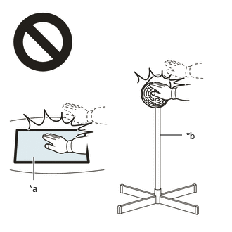 2.365,2 2.698,2 false 0.5,2.333 0.5,2.667 true 0.427,2.708 0.74,2.865 0.313,0.156 10 false *a 2.76,1.927 3.073,2.083 0.313,0.156 10 false *b
*a Heated Part *b Heat Light
- ·
Do not touch the heat light and heated parts.
·Touching the heat light may result in burns.
·Touching heated parts for a long time may result in burns.
- Standard:
Item Temperature Front Bumper Assembly 40 to 60°C (104 to 140°F) Front Corner Ultrasonic Sensor Retainer
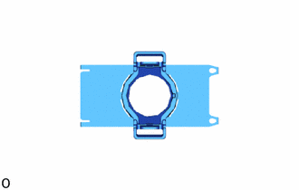
Remove the front corner ultrasonic sensor retainer.