SEAT CLIMATE CONTROL SEAT SYSTEM(for Gasoline Model) Climate Control System does not Operate on Passenger Side
DESCRIPTION
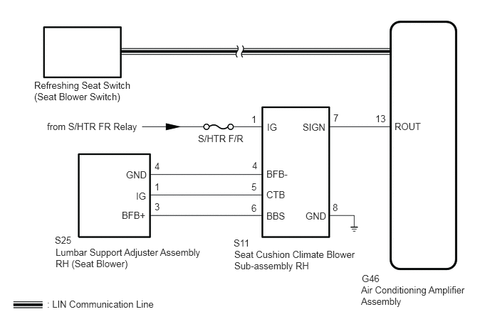
The air conditioning amplifier assembly receives front passenger side refreshing seat switch (seat blower switch) position signals when the engine switch is on (IG), and then transmits airflow amount signals to each seat climate blower.
WIRING DIAGRAM
CAUTION / NOTICE / HINT
- NOTICE:
- ·
If the battery voltage is low, the climate control seat system may not operate. When "High Power Consumption Partial Limit on AC/Heater Operation" is displayed on the multi-information display in the combination meter assembly, inspect the battery, referring to On-vehicle Inspection for the charging system.
·If the climate control seat system is operated when the battery voltage is low, due to the electrical load limit control that gives voltage supply priority to the power steering system, the climate control seat system may not operate. In this case, check the vehicle control history of the power steering system and check that "Battery Voltage Drop: X208F" is not stored before proceeding with troubleshooting.
- HINT:
-
Inspect the fuse related to this system before inspecting the suspected areas below.
PROCEDURE
Connect the GTS to the DLC3.
Turn the engine switch on (IG).
Turn the GTS on.
Enter the following menus: Body Electrical / Air Conditioner / Active Test.
Perform the Active Test according to the display on the GTS.
- Body Electrical > Air Conditioner > Active Test
-
Tester Display Measurement Item Control Range Diagnostic Note Front Right Seat Blower RH side seat blower operation OFF/ON -
- Body Electrical > Air Conditioner > Active Test
-
Tester Display Front Right Seat Blower - 50004 450 21
- Result:
Result Proceed to Both seat cushion seat blower and seatback seat blower operate A Only seat cushion seat blower does not operate B Only seatback seat blower does not operate C Both seat cushion seat blower and seatback seat blower do not operate D
A
B
C
D
Replace the refreshing seat switch (seat blower switch) with a new or known good one.
- Result:
Proceed to NEXT
NEXT
Check the climate control seat operation.
- OK:
The climate control seat operates normally.
- Result:
Proceed to OK NG
OK
NG
Disconnect the S25 lumbar support adjuster assembly RH (seat blower) connector.
Disconnect the S11 seat cushion climate blower sub-assembly RH connector.
Measure the resistance according to the value(s) in the table below.
- Standard Resistance:
Tester Connection Condition Specified Condition S25-4 (GND) - S11-4 (BFB-) Always Below 1 Ω S25-4 (GND) or S11-4 (BFB-) - Other terminals and body ground Always 10 kΩ or higher S25-1 (IG) - S11-5 (CTB) Always Below 1 Ω S25-1 (IG) or S11-5 (CTB) - Other terminals and body ground Always 10 kΩ or higher S25-3 (BFB+) - S11-6 (BBS) Always Below 1 Ω S25-3 (BFB+) or S11-6 (BBS) - Other terminals and body ground Always 10 kΩ or higher
- Result:
Proceed to OK NG
OK
NG
Replace the lumbar support adjuster assembly RH (seat blower) with a new or known good one.
- Result:
Proceed to NEXT
NEXT
Check the climate control seat operation.
- OK:
The climate control seat operates normally.
- Result:
Proceed to OK NG
OK
NG
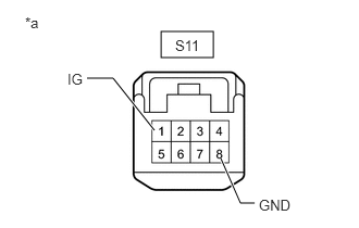
| *a | Front view of wire harness connector
(to Seat Cushion Climate Blower Sub-assembly RH) |
Disconnect the seat cushion climate blower sub-assembly RH connector.
Measure the voltage according to the value(s) in the table below.
- Standard Voltage:
Tester Connection Switch Condition Specified Condition S11-1 (IG) - Body ground Engine switch on (IG) 11 to 14 V S11-1 (IG) - Body ground Engine switch off Below 1 V
Measure the resistance according to the value(s) in the table below.
- Standard Resistance:
Tester Connection Condition Specified Condition S11-8 (GND) - Body ground Always Below 1 Ω
- Result:
Proceed to OK NG
OK
NG
Disconnect the S11 seat cushion climate blower sub-assembly RH connector.
Disconnect the G46 air conditioning amplifier assembly connector.
Measure the resistance according to the value(s) in the table below.
- Standard Resistance:
Tester Connection Condition Specified Condition S11-7 (SIGN) - G46-13 (ROUT) Always Below 1 Ω S11-7 (SIGN) or G46-13 (ROUT) - Other terminals and body ground Always 10 kΩ or higher
- Result:
Proceed to OK NG
OK
NG
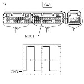
| *a | Component with harness connected
(Air Conditioning Amplifier Assembly) |
Check for pulses according to the value(s) in the table below.
| Item | Content |
|---|---|
| Tester Connection | G46-13 (ROUT) - Body ground |
| Tool Setting | 1 V/DIV., 1 ms/DIV. |
| Vehicle Condition | ·
Engine switch on (IG) ·
RH side refreshing seat switch (seat blower switch) operate |
- OK:
Waveform is similar to that shown in the illustration.
- Result:
Proceed to OK NG
OK
NG