THEFT DETERRENT / KEYLESS ENTRY SMART ENTRY AND START SYSTEM(for Start Function, Gasoline Model) P057162 Brake Switch "A" Signal Compare Failure
DESCRIPTION
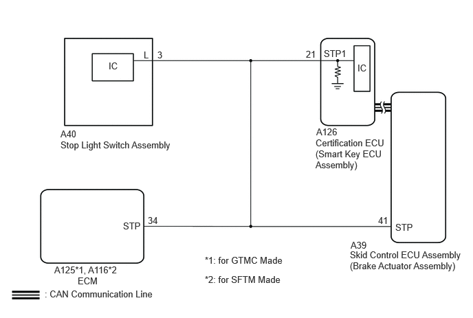
This DTC is stored when the brake signal sent via direct line and the brake signal sent via CAN communication do not match.
| DTC No. | Detection Item | DTC Detection Condition | Trouble Area | Note |
|---|---|---|---|---|
| P057162 | Brake Switch "A" Signal Compare Failure | The brake signal sent via direct line and the brake signal sent via CAN communication do not match. (1-trip detection logic*) | ·
Electronically controlled brake system ·
Stop light switch assembly ·
Certification ECU (smart key ECU assembly) ·
Wire harness or connector |
DTC Output Confirmation Operation:
Connect the cable to the negative (-) auxiliary battery terminal, release the brake pedal and wait at least 20 seconds. Then depress the brake pedal for 20 seconds or more. |
*: Only detected while a malfunction is present and the ignition switch is ON.
| Vehicle Condition when Malfunction Detected | Fail-safe Function when Malfunction Detected |
|---|---|
·
If there is a malfunction when the brake signal sent via direct line is on, the engine can be started by pressing the engine switch with the brake pedal released. ·
If there is a malfunction when the brake signal sent via direct line is off, the engine cannot be started by pressing the engine switch with the brake pedal depressed. -
With the electrical key transmitter sub-assembly in the cabin, even if an engine start operation is performed, the engine does not start (the key indicator display is not displayed on the multi-information display). However, the engine can be started by turning the ignition switch to ACC and then pressing and holding it. |
- |
| DTC No. | Data List and Active Test |
|---|---|
| P057162 | Power Source Control
·
Stop Light Switch |
WIRING DIAGRAM
CAUTION / NOTICE / HINT
- NOTICE:
- ·
When using the GTS with the ignition switch off, connect the GTS to the DLC3 and turn a courtesy light switch on and off at intervals of 1.5 seconds or less until communication between the GTS and the vehicle begins. Then select the vehicle type under manual mode and enter the following menus: Body Electrical / Entry&Start. While using the GTS, periodically turn a courtesy light switch on and off at intervals of 1.5 seconds or less to maintain communication between the GTS and the vehicle.
·The smart entry and start system (for Start Function) uses the LIN communication system and CAN communication system. Inspect the communication function by following How to Proceed with Troubleshooting. Troubleshoot the smart entry and start system (for Start Function) after confirming that the communication systems are functioning properly.
·When disconnecting the cable from the negative (-) battery terminal, some systems need to be initialized after the cable is reconnected.
·Before replacing the certification ECU (smart key ECU assembly), refer to Service Bulletin.
·After repair, confirm that no DTCs are output by performing "DTC Output Confirmation Operation".
PROCEDURE
Read the Data List according to the display on the GTS.
- Body Electrical > Power Source Control > Data List
-
Tester Display Measurement Item Range Normal Condition Diagnostic Note Stop Light Switch State of brake pedal OFF or ON OFF: Brake pedal released ·Use this item to determine if the stop light switch assembly is malfunctioning.
·The engine cannot be started when this item is OFF.
·If the stop light switch assembly is malfunctioning, the engine can be started by pressing and holding the engine switch for a certain period of time.
- Body Electrical > Power Source Control > Data List
-
Tester Display Stop Light Switch - 50003 454 206
- OK:
The GTS display changes correctly in response to the brake pedal operation.
- Result:
Result Proceed to The value of Stop Light Switch is OFF A The value of Stop Light Switch is not OFF B
A
B
Read the Data List according to the display on the GTS.
- Body Electrical > Power Source Control > Data List
-
Tester Display Measurement Item Range Normal Condition Diagnostic Note Stop Light Switch State of brake pedal OFF or ON ON: Brake pedal depressed ·Use this item to determine if the stop light switch assembly is malfunctioning.
·The engine cannot be started when this item is OFF.
·If the stop light switch assembly is malfunctioning, the engine can be started by pressing and holding the engine switch for a certain period of time.
- Body Electrical > Power Source Control > Data List
-
Tester Display Stop Light Switch - 50003 454 206
- OK:
The GTS display changes correctly in response to the brake pedal operation.
- Result:
Result Proceed to The value of Stop Light Switch is ON A The value of Stop Light Switch is not ON B
A
B
Pre-procedure1
Disconnect the A126 certification ECU (smart key ECU assembly) connector.
Disconnect the A40 stop light switch assembly connector.
Disconnect the A39 skid control ECU (brake actuator assembly) connector.
Disconnect the A125*1 or A116*2 ECM connector.
*1: for GTMC Made
*2: for SFTM Made
Procedure1
Measure the resistance according to the value(s) in the table below.
- Standard Resistance:
Tester Connection Condition Specified Condition A126-21 (STP1) - A40-3 (L) Always Below 1 Ω
- Result:
Proceed to OK NG
Post-procedure1
Connect the A126 certification ECU (smart key ECU assembly) connector.
Connect the A40 stop light switch assembly connector.
OK
NG
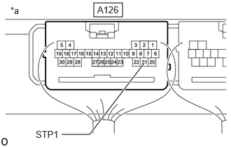
| *a | Component with harness connected
(Certification ECU (Smart Key ECU Assembly)) |
Measure the voltage according to the value(s) in the table below.
- Standard Voltage:
Tester Connection Condition Specified Condition A126-21 (STP1) - Body ground Brake pedal released 1 V or less A126-21 (STP1) - Body ground Brake pedal depressed 9 V or higher
- Result:
Proceed to OK NG
OK
NG