HEATING / AIR CONDITIONING AIR CONDITIONING SYSTEM(for Gasoline Model) P053015 Refrigerant Pressure Sensor Circuit Short to Battery or Open
DESCRIPTION
The air conditioning pressure sensor, which is installed to the high pressure side pipe to detect refrigerant pressure, sends a refrigerant pressure signal to the air conditioning amplifier assembly. The air conditioning amplifier assembly converts this signal to a pressure value according to the sensor characteristics and uses it to control the compressor.
| DTC No. | Detection Item | DTC Detection Condition | Trouble Area | Memory |
|---|---|---|---|---|
| P053015 | Refrigerant Pressure Sensor Circuit Short to Battery or Open | Diagnosis Condition:
Ignition switch ON Malfunction Status:
Open or short to +B in air conditioning pressure sensor circuit Detection Time:
Continuously for 4 seconds or more |
·
Air conditioning pressure sensor ·
Harness or connector ·
Air conditioning amplifier assembly |
Memorized |
| Vehicle Condition | |||
|---|---|---|---|
| Pattern 1 | Pattern 2 | ||
| Diagnosis Condition | Ignition switch ON | ○ | ○ |
| Malfunction | Open in air conditioning pressure sensor circuit | ○ | - |
| Short to +B in air conditioning pressure sensor circuit | - | ○ | |
| Detection Time | Continuously for 4 seconds or more | Continuously for 4 seconds or more | |
| Trip Count | 1 trip | 1 trip | |
- HINT:
-
If the conditions of either of these patterns are detected, a DTC will be stored
WIRING DIAGRAM
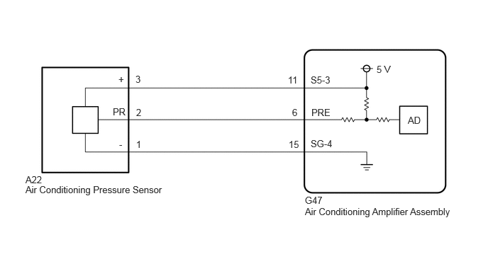
PROCEDURE
Pre-procedure1
Install a manifold gauge set.
Read the Data List according to the display on the GTS.
- Body Electrical > Air Conditioner > Data List
-
Tester Display Measurement Item Range Normal Condition Diagnostic Note Regulator Pressure Sensor Refrigerant gas pressure on high pressure side Min.: -32.768 MPaG
Max.: 32.767 MPaGActual refrigerant pressure displayed ·Refrigerant line (gas leak etc.)
·Air conditioning pressure sensor circuit malfunction
- Body Electrical > Air Conditioner > Data List
-
Tester Display Regulator Pressure Sensor - 50003 450 106
Procedure1
Compare the values displayed in the Data List and on the manifold gauge set.
- Result:
Result Proceed to The values displayed in the Data List and on the manifold gauge set does not match A The values displayed in the Data List and on the manifold gauge set match B
Post-procedure1
None
A
B
Pre-procedure1
Disconnect the A22 air conditioning pressure sensor connector.
Procedure1
Measure the resistance according to the value(s) in the table below.
- Standard Resistance:
Tester Connection Condition Specified Condition A22-1 (-) - Body ground Always Below 1 Ω
- Result:
Proceed to OK NG
Post-procedure1
None
OK
NG
Pre-procedure1
Disconnect the A22 air conditioning pressure sensor connector.
Procedure1
Measure the voltage according to the value(s) in the table below.
- Standard Voltage:
Tester Connection Switch Condition Specified Condition A22-2 (PR) - Body ground Ignition switch ON 3.0 to 5.25 V
- Result:
Result Proceed to Higher than 5.25 V A 3.0 to 5.25 V B Less than 3.0V C
Post-procedure1
None
A
B
C
Pre-procedure1
Disconnect the A22 air conditioning pressure sensor connector.
Disconnect the G47 air conditioning amplifier assembly connector.
Procedure1
Measure the resistance according to the value(s) in the table below.
- Standard Resistance:
Tester Connection Condition Specified Condition A22-2 (PR) or G47-6 (PRE) - Other terminals and body ground Always 10 kΩ or higher
- Result:
Proceed to OK NG
Post-procedure1
None
OK
NG
Pre-procedure1
Disconnect the A22 air conditioning pressure sensor connector.
Procedure1
Measure the resistance according to the value(s) in the table below.
- Standard Resistance:
Tester Connection Switch Condition Specified Condition A22-3 (+) - A22-2 (PR) Ignition switch ON 180 to 220 kΩ
- HINT:
-
After turning the ignition switch off, wait at least 30 seconds before performing the measurement.
- Result:
Proceed to OK NG
Post-procedure1
None
OK
NG
Pre-procedure1
Disconnect the A22 air conditioning pressure sensor connector.
Disconnect the G47 air conditioning amplifier assembly connector.
Procedure1
Measure the resistance according to the value(s) in the table below.
- Standard Resistance:
Tester Connection Condition Specified Condition A22-2 (PR) or G47-6 (PRE) - Other terminals and body ground Always 10 kΩ or higher A22-3 (+) or G47-11 (S5-3) - Other terminals and body ground Always 10 kΩ or higher
- Result:
Proceed to OK NG
Post-procedure1
None
OK
NG
Pre-procedure1
Disconnect the A22 air conditioning pressure sensor connector.
Disconnect the G47 air conditioning amplifier assembly connector.
Procedure1
Measure the resistance according to the value(s) in the table below.
- Standard Resistance:
Tester Connection Condition Specified Condition A22-2 (PR) - G47-6 (PRE) Always Below 1 Ω
- Result:
Proceed to OK NG
Post-procedure1
None
OK
NG
Pre-procedure1
Disconnect the A22 air conditioning pressure sensor connector.
Disconnect the G47 air conditioning amplifier assembly connector.
Procedure1
Measure the resistance according to the value(s) in the table below.
- Standard Resistance:
Tester Connection Condition Specified Condition A22-1 (-) - G47-15 (SG-4) Always Below 1 Ω
- Result:
Proceed to OK NG
Post-procedure1
None
OK
NG