DOOR LOCK POWER DOOR LOCK CONTROL SYSTEM Only Back Door cannot be Opened
DESCRIPTION
The main body ECU (multiplex network body ECU) receives signals from the back door opener switch assembly. Then, the main body ECU (multiplex network body ECU) activates the back door lock motor.
WIRING DIAGRAM
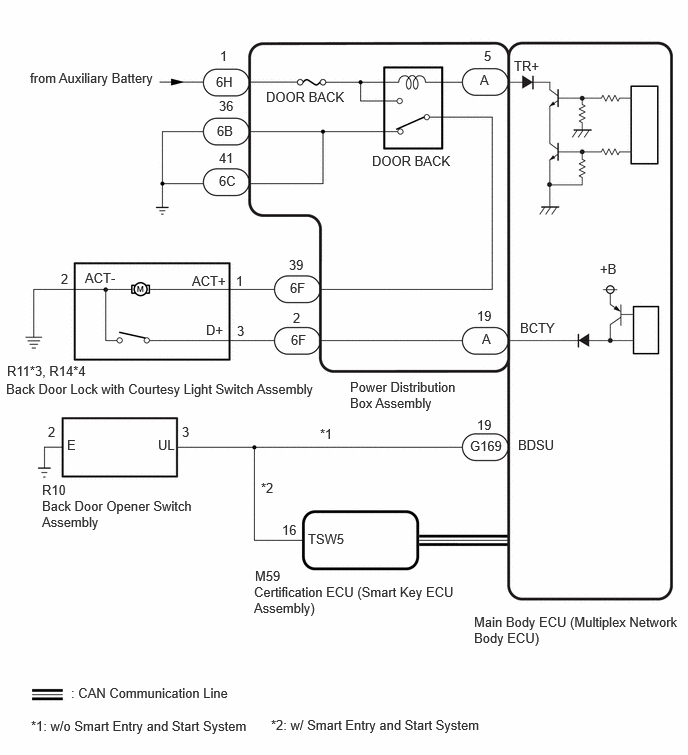
CAUTION / NOTICE / HINT
- NOTICE:
- ·
When using the GTS with the vehicle ignition switch off, connect the GTS to the DLC3 and turn a courtesy light switch on and off at intervals of 1.5 seconds or less until communication between the GTS and the vehicle begins.
·Inspect the fuses for circuits related to this system before performing the following procedure.
·The power door lock control system uses the CAN communication system. Inspect the communication function by following How to Proceed with Troubleshooting. Troubleshoot the power door lock control system after confirming that the communication systems are functioning properly.
·If the main body ECU (multiplex network body ECU) is replaced, refer to Service Bulletin (w/ Smart Entry and Start System).
PROCEDURE
Perform the Active Test according to the display on the GTS.
- Body Electrical > Main Body > Active Test
-
Tester Display Measurement Item Control Range Diagnostic Note Trunk Lid / Back Door Open Back door lock motor OFF or ON -
- Body Electrical > Main Body > Active Test
-
Tester Display Trunk Lid / Back Door Open - 50004 449 15
- OK:
The back door lock with courtesy light switch assembly unlatches when ON is selected.
- Result:
Result Proceed to OK (w/ Entry Function) A OK (w/o Entry Function) B NG C
A
for HV Model:
for Gasoline Model:
B
C
- Result:
Proceed to OK NG
OK
NG
Disconnect the R10 back door opener switch assembly connector.
Disconnect the G169 main body ECU (multiplex network body ECU) connector.
Measure the resistance according to the value(s) in the table below.
- Standard Resistance:
Tester Connection Condition Specified Condition R10-3 (UL) - G169-19 (BDSU) Always Below 1 Ω R10-2 (E) - Body ground Always Below 1 Ω R10-3 (UL) or G169-19 (BDSU) - Other terminals and body ground Always 10 kΩ or higher
- Result:
Proceed to OK NG
OK
NG
- Result:
Proceed to OK NG
OK
NG
Click hereVehicle Interior>DOOR LOCK>BACK DOOR LOCK>REMOVAL201910,999999,_58,_083092,_0403682,RM100000001JUF3,
Disconnect the R11 back door lock with courtesy light switch assembly connector.
Disconnect the 6F power distribution box assembly connector.
Measure the resistance according to the value(s) in the table below.
- Standard Resistance:
Tester Connection Condition Specified Condition R11-1 (ACT+) - 6F-39 Always Below 1 Ω R11-3 (D+) - 6F-2 Always Below 1 Ω R11-2 (ACT-) - Body ground Always Below 1 Ω R11-1 (ACT+) or 6F-39 - Other terminals and body ground Always 10 kΩ or higher R11-3 (D+) or 6F-2 - Other terminals and body ground Always 10 kΩ or higher
- Result:
Proceed to OK NG
OK
NG
Remove the main body ECU (multiplex network body ECU) from the power distribution box assembly.
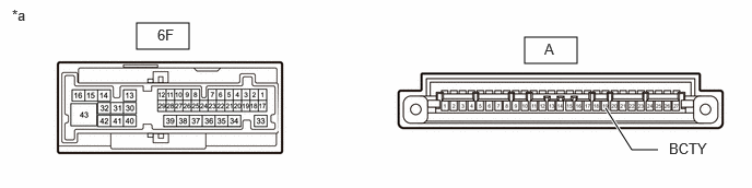
| *a | Component without harness connected
(Power Distribution Box Assembly) |
- | - |
Measure the resistance according to the value(s) in the table below.
- Standard Resistance:
Tester Connection Condition Specified Condition A-19 (BCTY) - 6F-2 Always Below 1 Ω
- Result:
Proceed to OK NG
OK
NG
Disconnect the power distribution box assembly connectors.
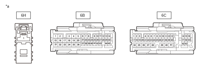
| *a | Front view of wire harness connector
(to Power Distribution Box Assembly) |
- | - |
Measure the voltage according to the value(s) in the table below.
- Standard Voltage:
Tester Connection Switch Condition Specified Condition 6H-1 - Body ground Ignition switch off 11 to 14 V
Measure the resistance according to the value(s) in the table below.
- Standard Resistance:
Tester Connection Condition Specified Condition 6B-36 - Body ground Always Below 1 Ω 6C-41 - Body ground Always Below 1 Ω
- Result:
Proceed to OK NG
OK
NG
Remove the main body ECU (multiplex network body ECU) from the power distribution box assembly.
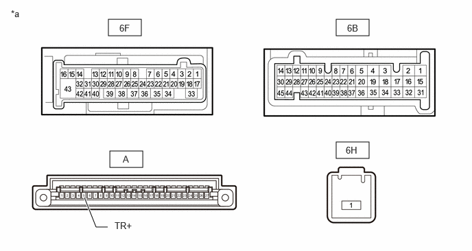
| *a | Component without harness connected
(Power Distribution Box Assembly) |
- | - |
Measure the resistance according to the value(s) in the table below.
- Standard Resistance:
Tester Connection Condition Specified Condition 6F-39 - 6B-36 Auxiliary battery voltage applied to terminals 6H-1 and A-5 10 kΩ or higher 6F-39 - 6B-36 Auxiliary battery voltage not applied to terminals 6H-1 and A-5 Below 1 Ω
Measure the voltage according to the value(s) in the table below.
- Standard Voltage:
Tester Connection Condition Specified Condition 6F-39 - Auxiliary battery negative (-) terminal Auxiliary battery voltage applied to terminals 6H-1 and A-5 11 to 14 V
- Result:
Proceed to OK NG
OK
NG