K121 CVT CONTINUOUSLY VARIABLE TRANSAXLE SYSTEM P070562 Transmission Range Sensor "A" Signal Compare Failure
DESCRIPTION
The shift lever position sensor and transmission control switch (shift lock control unit assembly) detect the shift lever position and send signals to the ECM.
| DTC No. | Detection Item | DTC Detection Condition | Trouble Area | MIL | DTC Output from | Priority | Note |
|---|---|---|---|---|---|---|---|
| P070562 | Transmission Range Sensor "A" Signal Compare Failure | Either of the following conditions is met for 2 seconds or more (1-trip detection logic).
·
A malfunction in the P, R, N or D circuit is detected based on the shift sensor input pattern. ·
The input pattern of the shift lever position sensor circuit is P, R or N with the shift lever in M. |
·
Wire harness or connector ·
Shift lever position sensor ·
ECM |
Comes on | Engine | A | SAE Code:
P0705 |
MONITOR DESCRIPTION
This DTC indicates a problem with the shift lever position sensor, transmission control switch or wire harness of their circuits.
The shift lever position sensor sends a signal to the ECM according to the shift lever position (P, R, N or D).
If the ECM detects a malfunction in the signal of the shift position sensor, it is suspected that a sensor or related component is malfunctioning. The ECM will then illuminate the MIL and store a DTC.
CONFIRMATION DRIVING PATTERN
- HINT:
- ·
After repairs have been completed, clear the DTCs and then check that the vehicle has returned to normal by performing the following All Readiness check procedure.
·When clearing the permanent DTCs, refer to the Clear Permanent DTC procedure.
Clear the DTCs (even if no DTCs are stored, perform the clear DTC procedure).
Turn the ignition switch off and wait for 2 minutes or more.
Wait with the shift lever in each position (P, R, N or D) for 2 seconds or more each with the ignition switch ON. [*1]
Wait for 2 seconds or more with the shift lever in M. [*2]
- HINT:
-
[*1] and [*2]: Normal judgment procedure.
-
The normal judgment procedure is used to complete DTC judgment and also used when clearing permanent DTCs.
Enter the following menus: Powertrain / Engine / Utility / All Readiness.
Input the DTC: P070562.
Check the DTC judgment result.
| GTS Display | Description |
|---|---|
| NORMAL | ·
DTC judgment completed ·
System normal |
| ABNORMAL | ·
DTC judgment completed ·
System abnormal |
| INCOMPLETE | ·
DTC judgment not completed ·
Perform driving pattern after confirming DTC enabling conditions |
| N/A | ·
Unable to perform DTC judgment ·
Number of DTCs which do not fulfill DTC preconditions has reached ECU memory limit |
- HINT:
- ·
If the judgment result shows NORMAL, the system is normal.
·If the judgment result shows ABNORMAL, the system has a malfunction.
·If the judgment result shows INCOMPLETE or N/A, perform the normal judgment procedure again.
WIRING DIAGRAM
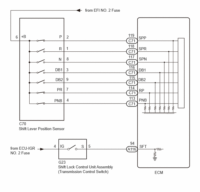
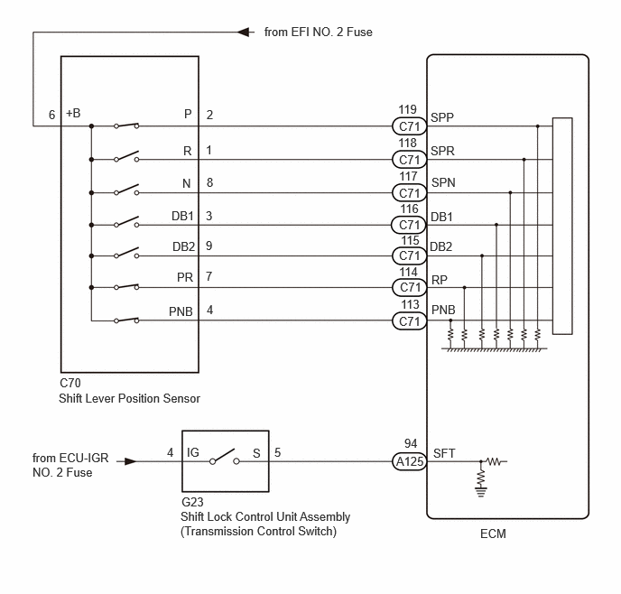
CAUTION / NOTICE / HINT
- NOTICE:
- ·
Perform the universal trip to clear permanent DTCs.
·Perform registration and/or initialization when parts related to the continuously variable transaxle system are replaced.
·Check that no DTCs are stored after performing initialization.
·Inspect the fuses for circuits related to this system before performing the following inspection procedure.
PROCEDURE
According to the display on the GTS, read the Data List.
- Powertrain > Engine > Data List
-
Tester Display Measurement Item Range Normal Condition Diagnostic Note Shift Sensor Switch DB1 Shift lever position sensor status OFF or ON ·ON: Shift lever in D
·OFF: Shift lever in any position other than D
When the shift lever position displayed on the GTS differs from the actual position, the adjustment of the shift lever position sensor or shift cable may be incorrect. Shift Sensor Switch DB2 Shift lever position sensor status OFF or ON ·ON: Shift lever in D
·OFF: Shift lever in any position other than D
When the shift lever position displayed on the GTS differs from the actual position, the adjustment of the shift lever position sensor or shift cable may be incorrect. Shift Sensor Switch SPN Shift lever position sensor status OFF or ON ·ON: Shift lever in N
·OFF: Shift lever in any position other than N
When the shift lever position displayed on the GTS differs from the actual position, the adjustment of the shift lever position sensor or shift cable may be incorrect. Shift Sensor Switch SPR Shift lever position sensor status OFF or ON ·ON: Shift lever in R
·OFF: Shift lever in any position other than R
When the shift lever position displayed on the GTS differs from the actual position, the adjustment of the shift lever position sensor or shift cable may be incorrect. Shift Sensor Switch SPP Shift lever position sensor status OFF or ON ·ON: Shift lever in P
·OFF: Shift lever in any position other than P
When the shift lever position displayed on the GTS differs from the actual position, the adjustment of the shift lever position sensor or shift cable may be incorrect. Shift Sensor Switch PNB Shift lever position sensor status OFF or ON ·ON: Shift lever in P or N
·OFF: Shift lever in any position other than P or N
When the shift lever position displayed on the GTS differs from the actual position, the adjustment of the shift lever position sensor or shift cable may be incorrect. Shift Sensor Switch RP Shift lever position sensor status OFF or ON ·ON: Shift lever in P or R
·OFF: Shift lever in any position other than P or R
When the shift lever position displayed on the GTS differs from the actual position, the adjustment of the shift lever position sensor or shift cable may be incorrect.
- Powertrain > Engine > Data List
-
Tester Display Shift Sensor Switch DB1 Shift Sensor Switch DB2 Shift Sensor Switch SPN Shift Sensor Switch SPR Shift Sensor Switch SPP Shift Sensor Switch PNB Shift Sensor Switch RP - 50003 372 1624,1630,1625,1626,1627,1628,1629
- Standard:
Data List Shift Position P R N D Shift Sensor Switch (DB1) OFF OFF OFF ON Shift Sensor Switch (DB2) OFF OFF OFF ON Shift Sensor Switch (SPN) OFF OFF ON OFF Shift Sensor Switch (SPR) OFF ON OFF OFF Shift Sensor Switch (SPP) ON OFF OFF OFF Shift Sensor Switch (PNB) ON OFF ON OFF Shift Sensor Switch (RP) ON ON OFF OFF
- Result:
Proceed to OK NG
OK
NG
According to the display on the GTS, read the Data List.
- Powertrain > Engine > Data List
-
Tester Display Measurement Item Range Normal Condition Diagnostic Note Shift SW Status (S Range) Transmission control switch status OFF or ON OFF: Shift lever not in M, "+" or "-" -
- Powertrain > Engine > Data List
-
Tester Display Shift SW Status (S Range) - 50003 372 27
- Result:
Result Proceed to The value of Shift SW Status (S Range) is OFF A The value of Shift SW Status (S Range) is not OFF B
A
B
Pre-procedure1
Disconnect the G23 shift lock control unit assembly connector.
Procedure1
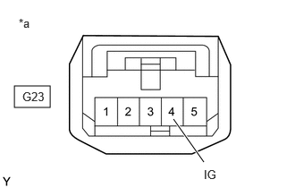
| *a | Front view of wire harness connector (to Shift Lock Control Unit Assembly (Transmission Control Switch)) |
Measure the voltage according to the value(s) in the table below.
- Standard Voltage:
Tester Connection Condition Specified Condition G23-4 (IG) - Body ground Ignition switch ON 11 to 14 V G23-4 (IG) - Body ground Ignition switch off Below 1 V
- Result:
Proceed to OK NG
Post-procedure1
Connect the G23 shift lock control unit assembly connector.
OK
NG
Click hereDrivetrain>K121 (CVT)>SHIFT LEVER>INSPECTION202304,999999,_52,_138176,_0579406,RM1000000029ENQ,
- Result:
Proceed to OK NG
OK
NG
Click hereDrivetrain>K121 (CVT)>SHIFT LEVER>REMOVAL202304,999999,_52,_138176,_0579406,RM1000000029ENO,
Pre-procedure1
Disconnect the G23 shift lock control unit assembly connector.
for SFTM Made:
Disconnect the A116 ECM connector.
for GTMC Made:
Disconnect the A125 ECM connector.
Procedure1
Measure the resistance according to the value(s) in the table below.
- Standard Resistance (for SFTM Made):
Tester Connection Condition Specified Condition G23-5 (S) - A116-94 (SFT) Always Below 1 Ω G23-5 (S) or A116-94 (SFT) - Body ground Always 10 kΩ or higher
- Standard Resistance (for GTMC Made):
Tester Connection Condition Specified Condition G23-5 (S) - A125-94 (SFT) Always Below 1 Ω G23-5 (S) or A125-94 (SFT) - Body ground Always 10 kΩ or higher
- Result:
Proceed to OK NG
Post-procedure1
for SFTM Made:
Connect the A116 ECM connector.
for GTMC Made:
Connect the A125 ECM connector.
Connect the G23 shift lock control unit assembly connector.
OK
NG
- HINT:
-
for M20C-FKS:
-
for M20D-FKS:
- Result:
Proceed to NEXT
NEXT
for Registration: Click hereDrivetrain>K121 (CVT)>CONTINUOUSLY VARIABLE TRANSAXLE SYSTEM>REGISTRATION202304,999999,_52,_138176,_0584691,RM1000000029HF6,
for Initialization: Click hereDrivetrain>K121 (CVT)>CONTINUOUSLY VARIABLE TRANSAXLE SYSTEM>INITIALIZATION202409,999999,_52,_138176,_0584691,RM100000002NRHB,
Pre-procedure1
Disconnect the C70 shift lever position sensor connector.
Procedure1
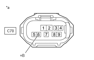
| *a | Front view of wire harness connector (to Shift Lever Position Sensor) |
Measure the voltage according to the value(s) in the table below.
- Standard Voltage:
Tester Connection Condition Specified Condition C70-6 (+B) - Body ground Ignition switch ON 11 to 14 V C70-6 (+B) - Body ground Ignition switch off Below 1 V
- Result:
Proceed to OK NG
Post-procedure1
Connect the C70 shift lever position sensor connector.
OK
NG
- Result:
Proceed to OK NG
OK
NG
Pre-procedure1
Disconnect the C70 shift lever position sensor connector.
Disconnect the C71 ECM connector.
Procedure1
Measure the resistance according to the value(s) in the table below.
- Standard Resistance:
Tester Connection Condition Specified Condition C70-2 (P) - C71-119 (SPP) Always Below 1 Ω C70-1 (R) - C71-118 (SPR) Always Below 1 Ω C70-8 (N) - C71-117 (SPN) Always Below 1 Ω C70-3 (DB1) - C71-116 (DB1) Always Below 1 Ω C70-9 (DB2) - C71-115 (DB2) Always Below 1 Ω C70-7 (PR) - C71-114 (RP) Always Below 1 Ω C70-4 (PNB) - C71-113 (PNB) Always Below 1 Ω C70-2 (P) or C71-119 (SPP) - Body ground and other terminals Always 10 kΩ or higher C70-1 (R) or C71-118 (SPR) - Body ground and other terminals Always 10 kΩ or higher C70-8 (N) or C71-117 (SPN) - Body ground and other terminals Always 10 kΩ or higher C70-3 (DB1) or C71-116 (DB1) - Body ground and other terminals Always 10 kΩ or higher C70-9 (DB2) or C71-115 (DB2) - Body ground and other terminals Always 10 kΩ or higher C70-7 (PR) or C71-114 (RP) - Body ground and other terminals Always 10 kΩ or higher C70-4 (PNB) or C71-113 (PNB) - Body ground and other terminals Always 10 kΩ or higher
- Result:
Proceed to OK NG
Post-procedure1
Connect the C71 ECM connector.
Connect the C70 shift lever position sensor connector.
OK
NG
- HINT:
-
for M20C-FKS:
-
for M20D-FKS:
- Result:
Proceed to NEXT
NEXT
for Registration: Click hereDrivetrain>K121 (CVT)>CONTINUOUSLY VARIABLE TRANSAXLE SYSTEM>REGISTRATION202304,999999,_52,_138176,_0584691,RM1000000029HF6,
for Initialization: Click hereDrivetrain>K121 (CVT)>CONTINUOUSLY VARIABLE TRANSAXLE SYSTEM>INITIALIZATION202409,999999,_52,_138176,_0584691,RM100000002NRHB,