HYBRID / BATTERY CONTROL HYBRID CONTROL SYSTEM P0AA649 Hybrid/EV Battery Voltage System Isolation Internal Electronic Failure P1C7C49 Hybrid/EV Battery Voltage System Isolation (A/C Area) Internal Electronic Failure P1C7D49 Hybrid/EV Battery Voltage System Isolation (Hybrid/EV Battery Area) Internal Electronic Failure P1C7E49 Hybrid/EV Battery Voltage System Isolation (Transaxle Area) Internal Electronic Failure P1C7F49 Hybrid/EV Battery Voltage System Isolation (Direct Current Area) Internal Electronic Failure P1C8049 Hybrid/EV Battery Voltage System Isolation (Rear Motor Area) Internal Electronic Failure
DESCRIPTION
The hybrid vehicle control ECU assembly monitors the battery ECU assembly and detects insulation malfunctions in the high-voltage system.
| DTC No. | Detection Item | DTC Detection Condition | Trouble Area | MIL | Warning Indicate | Note |
|---|---|---|---|---|---|---|
| P0AA649 | Hybrid/EV Battery Voltage System Isolation Internal Electronic Failure | Insulation resistance between the high-voltage circuit and the body has decreased.*1
(1 trip detection logic) |
·
Inverter with converter assembly ·
HV floor under wire ·
HV battery junction block assembly ·
Battery ECU assembly ·
Hybrid battery terminal block ·
No. 1 HV supply stack sub-assembly ·
No. 2 HV supply stack sub-assembly ·
Electric vehicle battery plug assembly ·
Hybrid vehicle transaxle assembly ·
Motor cable ·
Air conditioning system ·
Air conditioning wire ·
Rear traction motor with transaxle assembly |
Does not come on | Master Warning:
Comes on |
SAE Code:
P0AA6 |
| P1C7C49 | Hybrid/EV Battery Voltage System Isolation (A/C Area) Internal Electronic Failure | Insulation resistance of the compressor with motor assembly or air conditioning inverter has decreased.*2
(1 trip detection logic) |
Air conditioning system | Does not come on | Master Warning:
Comes on |
SAE Code:
P0AA6 |
| P1C7D49 | Hybrid/EV Battery Voltage System Isolation (Hybrid/EV Battery Area) Internal Electronic Failure | Insulation resistance of the HV battery, battery ECU assembly or SMR has decreased.*2
(1 trip detection logic) |
·
HV battery junction block assembly ·
Battery ECU assembly ·
Hybrid battery terminal block ·
No. 1 HV supply stack sub-assembly ·
No. 2 HV supply stack sub-assembly ·
Electric vehicle battery plug assembly |
Does not come on | Master Warning:
Comes on |
SAE Code:
P0AA6 |
| P1C7E49 | Hybrid/EV Battery Voltage System Isolation (Transaxle Area) Internal Electronic Failure | Insulation resistance of the hybrid vehicle transaxle assembly or inverter for the generator (MG1) and motor (MG2) has decreased.*2
(1 trip detection logic) |
·
Hybrid vehicle transaxle assembly ·
Motor cable ·
Inverter with converter assembly |
Does not come on | Master Warning:
Comes on |
SAE Code:
P0AA6 |
| P1C7F49 | Hybrid/EV Battery Voltage System Isolation (Direct Current Area) Internal Electronic Failure | Insulation resistance of the inverter for the generator (MG1), motor (MG2) and rear motor (MGR), A/C inverter, SMR or HV floor under wire has decreased.*2
(1 trip detection logic) |
·
Inverter with converter assembly ·
HV floor under wire ·
HV battery junction block assembly ·
Air conditioning system ·
Air conditioning wire |
Does not come on | Master Warning:
Comes on |
SAE Code:
P0AA6 |
| P1C8049 | Hybrid/EV Battery Voltage System Isolation (Rear Motor Area) Internal Electronic Failure | Insulation resistance of the rear motor area has decreased.*2
(1 trip detection logic) |
·
Inverter with converter assembly ·
Rear traction motor with transaxle assembly ·
HV floor under wire (rear traction motor cable) ·
Rear traction motor cable |
Does not come on | Master Warning:
Comes on |
SAE Code:
P0AA6 |
- HINT:
- ·
*1: The insulation malfunction detection circuit in the battery ECU assembly monitors the insulation resistance between the high voltage circuits and body. If the insulation resistance decreases, the hybrid vehicle control ECU assembly stores DTC P0AA649 and illuminates the master warning first regardless of malfunction area.
Depending on the vehicle condition, the high voltage circuit insulation resistance may return to normal. So if DTC P0AA649 is output, complete the following steps as soon as possible.
·*2: If the following operations are performed within the same trip after DTC P0AA649 is stored, just one of the related DTCs (P1C7C49, P1C7D49, P1C7E49, P1C7F49 or P1C8049) will be stored.
(a)Apply the parking brake firmly.
- NOTICE:
-
Perform this test with the AUTO function (shift-linked function) of the electric parking brake system off.
- HINT:
-
When the parking brake indicator (red) is illuminated after the electric parking brake switch assembly has been pulled to the lock side, the maximum amount of braking force is applied if the electric parking brake switch assembly is pulled to the lock side one more time.
(b)Wait for 1 minute or more with the vehicle stopped, the brake pedal firmly depressed, the power switch on (READY), shift lever in D and the air conditioning system on (Lo/MAX COOL, blower speed HI).
(c)Turn the power switch off and wait for 2 minutes or more.
- HINT:
- ·
DTCs and freeze frame data are useful information in determining the malfunctioning part. Before performing diagnosis, make sure to check and make a note of all output DTCs and freeze frame data. (Even if a high-voltage insulation malfunction cannot be reproduced, once stored, insulation malfunction DTCs will not be cleared unless the clear operation is performed.)
·When the insulation resistance of the HV battery area decreases and the power switch is turned on (IG), DTC P1C7D49 is stored within 2 minutes.
·When measuring insulation resistance using a megohmmeter, measure the resistance while jiggling the high voltage wire harness.
| DTC No. | Data List |
|---|---|
| P0AA649 | ·
Short Wave Highest Value Level ·
Hybrid/EV Battery Voltage ·
VL-Voltage before Boosting ·
VL-Voltage before Boosting for Rear Motor ·
VH-Voltage after Boosting ·
Boost Ratio ·
A/C Consumption Power ·
SMRP Status ·
SMRB Status ·
SMRG Status ·
Generator Inverter Shutdown Status ·
Motor Inverter Shutdown Status ·
Rear Motor Inverter Shutdown Status ·
Insulation Resistance Division Check Completion using MG Inv ·
Insulation Resistance Division Check Completion using A/C Inv ·
Insulation Resistance Division Check Completion using SMR ·
Insulation Resistance Division Check Completion using Rear Motor Inv ·
Short Wave Highest Value Availability just after MG Inv On/Off ·
Short Wave Highest Value Availability just after A/C Inv On/Off ·
Short Wave Highest Value Availability just after SMR On/Off ·
Short Wave Highest Value Availability just after Rear Motor Inv On/Off |
| P1C7C49 | |
| P1C7D49 | |
| P1C7E49 | |
| P1C7F49 | |
| P1C8049 |
Use the following items as a reference when duplicating the vehicle conditions at the time when the malfunction occurred.
Vehicle Speed
Engine Run Time
Auxiliary Battery Voltage
Distance from DTC Cleared
Ready Signal
Hybrid/EV Battery SOC
CONFIRMATION DRIVING PATTERN
CONFIRMATION AFTER REPLACING PARTS
- HINT:
-
After repair has been completed, clear the DTC and then check that the vehicle has returned to normal by performing the following All Readiness check procedure. (Do not turn the power switch off (READY off) during this inspection.)
Connect the GTS to the DLC3.
Turn the power switch on (IG) and turn the GTS on.
Clear the DTCs (even if no DTCs are stored, perform the clear DTC procedure).
Turn the power switch off and wait for 2 minutes or more.
Apply the parking brake and secure the wheels using chocks.
- NOTICE:
-
Perform this test with the AUTO function (shift-linked function) of the electric parking brake system off.
- HINT:
-
When the parking brake indicator (red) is illuminated after the electric parking brake switch assembly has been pulled to the lock side, the maximum amount of braking force is applied if the electric parking brake switch assembly is pulled to the lock side one more time.
When the vehicle is stationary, turn the power switch on (READY) with shift lever in P and wait for 1 minute or more.
Turn the air conditioning system on (MAX COLD, blower speed HI).
While depressing the brake pedal without depressing the accelerator pedal, move the shift lever to D and wait for 5 minutes.
- If step A is performed within the same trip after DTC P0AA649 is stored, the parts with insufficient insulation resistance will be determined and a DTC (P1C7C49, P1C7D49, P1C7E49, P1C7F49 or P1C8049) will be stored.
- If no DTCs are output, proceed to the next step.
Drive the vehicle for approximately 5 minutes referring to the following freeze frame data items: "Vehicle Speed", "Shift Position", "Accelerator Position", "Engine Speed", "Coolant Temperature", "Master Cylinder Control Torque", "Inverter Coolant Water Temperature", "Generator Inverter Calculated Temperature" and "Motor Inverter Temperature"
(If the freeze frame data item "Vehicle Speed" is 10 km/h (6 mph) or less, drive the vehicle at 10 km/h (6 mph) or more.)
- If step A is performed within the same trip after DTC P0AA649 is stored, the parts with insufficient insulation resistance will be determined and a DTC (P1C7C49, P1C7D49, P1C7E49, P1C7F49 or P1C8049) will be stored.
- If DTC P0AA649 is output, complete Step A immediately as quickly as possible.
Wait for 1 minute or more with the vehicle stopped, the power switch on (READY), shift lever in P and the air conditioning system on (Lo/COOL MAX, blower speed HI), then turn the power switch off and wait for 2 minutes or more. (Step A)
Turn the power switch on (IG) and turn the GTS on.
Enter the following menus: Powertrain / Hybrid Control / Utility / All Readiness.
Check the DTC judgment result.
- HINT:
- ·
If the judgment result shows NORMAL, the system is normal.
·If the judgment result shows ABNORMAL, the system has a malfunction.
·If the judgment result shows INCOMPLETE, perform driving pattern again.
WIRING DIAGRAM
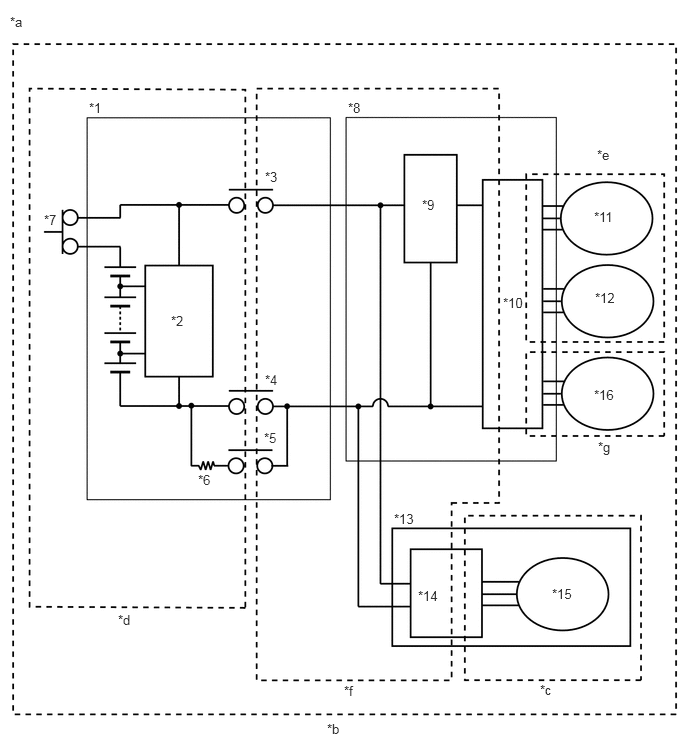
| *1 | HV Battery | *2 | Battery ECU assembly |
| *3 | SMRB | *4 | SMRG |
| *5 | SMRP | *6 | System Main Resistor |
| *7 | Service Plug Grip | *8 | Inverter with Converter Assembly |
| *9 | Boost Converter | *10 | Inverter |
| *11 | Generator (MG1) | *12 | Motor (MG2) |
| *13 | Compressor with Motor Assembly | *14 | A/C Inverter |
| *15 | A/C Motor | *16 | Rear Motor (MGR) |
| *a | High-voltage Areas | *b | DTC P0AA649 Vehicle Insulation Resistance Reduction Area |
| *c | DTC P1C7C49 Air Conditioning System Area | *d | DTC P1C7D49 HV Battery Area |
| *e | DTC P1C7E49 Hybrid Vehicle Transaxle Assembly Area or Inverter with Converter Assembly AC (Alternation Current) Section Area | *f | DTC P1C7F49 High Voltage Direct Current Area |
| *g | DTC P1C8049 Rear Motor Area | - | - |
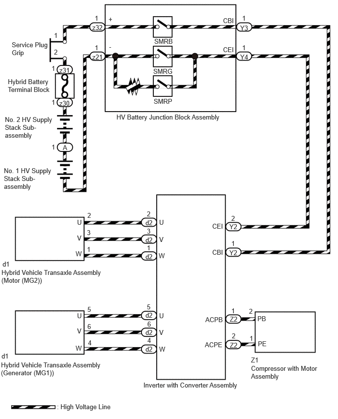
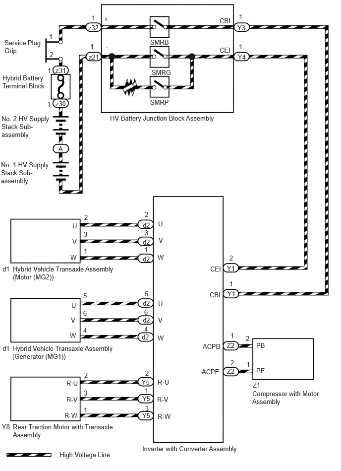
SYSTEM DESCRIPTION
- HINT:
-
If a decrease in insulation resistance cannot be confirmed using a megohmmeter, check "Short Wave Highest Value Level" in the Data List.
SHORT WAVE HIGHEST VALUE LEVEL
"Short Wave Highest Value Level" shows a decrease in insulation resistance. When insulation resistance decreases, "Insulation Lower" will be displayed. However, even though the insulation resistance of the vehicle is normal, "Short Wave Highest Value Level" may decrease, so that "Not Judge" will be displayed for any of the following conditions.
Within approximately 1 minute since the power switch was turned on (IG).
When the system voltages ("Hybrid/EV Battery Voltage", "VL-Voltage before Boosting", "VL-Voltage before Boosting for Rear Motor" and "VH-Voltage after Boosting") are changing.
During boosting. If the Data List item "Boost Ratio" is not 0% or within a few seconds of it becoming 0%. (The values of "Hybrid/EV Battery Voltage", "VL-Voltage before Boosting", "VL-Voltage before Boosting for Rear Motor" and "VH-Voltage after Boosting" are about the same when not boosting.)
When "No" is displayed for any of the following Data List items:
- Short Wave Highest Value Availability just after MG Inv On/Off
- Short Wave Highest Value Availability just after A/C Inv On/Off
- Short Wave Highest Value Availability just after SMR On/Off
- Short Wave Highest Value Availability just after Rear Motor Inv On/Off
When "Short Wave Highest Value Level" shows "Insulation Lower LV3", insulation resistance will be close to 0 Ω. In this case, damage to a high-voltage cable or hybrid component (high-voltage), or a short to body ground due to intrusion of foreign matter, such as metal particles, can be suspected.
RELATED FREEZE FRAME DATA
If problem symptoms cannot be reproduced and a malfunction still exists after replacing a part as instructed, checking the following freeze frame data can help determine a trouble area.
| Freeze Frame Data | Diagnostic Note |
|---|---|
| Short Wave Highest Value Level | Indicates that the insulation resistance has decreased. |
·
VL-Voltage before Boosting ·
VL-Voltage before Boosting for Rear Motor ·
VH-Voltage after Boosting ·
Hybrid/EV Battery Voltage ·
Boost Ratio |
During boosting (when "Boost Ratio" is not 0%), or when "VL-Voltage before Boosting", "VL-Voltage before Boosting for Rear Motor", "VH-Voltage after Boosting" or "Hybrid/EV Battery Voltage" is varying, "Short Wave Highest Value Level" may decrease even though the insulation resistance is normal. |
·
SMRP Status ·
SMRB Status ·
SMRG Status |
When "SMRP Status", "SMRB Status" and "SMRG Status" are all OFF, the insulation malfunction detection circuit detects a decrease in insulation resistance in the HV battery area ((*d) in the wiring diagram).
Example:
When the power switch is turned on (IG) (not on (READY)), all 3 system main relays are off and it is suspected that the HV battery assembly is disconnected from the high voltage circuits. If "Short Wave Highest Value Level" decreases a few minutes after the power switch is turned on (IG) (not on (READY)), the HV battery assembly may have an insulation malfunction. |
| Motor Inverter Shutdown Status | When "Motor Inverter Shutdown Status" is ON, the insulation malfunction detection circuit cannot detect a decrease in insulation resistance in the motor system AC (alternating current) section (motor (MG2) side of (*e) in the wiring diagram).
The motor system AC (alternating current) section includes the motor (MG2) in the hybrid vehicle transaxle assembly, motor cables and the AC (alternating current) section of the motor drive circuit in the inverter with converter assembly. |
| Generator Inverter Shutdown Status | When "Generator Inverter Shutdown Status" is ON, the insulation malfunction detection circuit cannot detect a decrease in insulation resistance in the generator system AC (alternating current) section (generator (MG1) side of (*e) in the wiring diagram).
The generator system AC (alternating current) section includes the generator (MG1) in the hybrid vehicle transaxle assembly, generator cables and the AC (alternating current) section of the generator drive circuit in the inverter with converter assembly. |
| Rear Motor Inverter Shutdown Status | When "Rear Motor Inverter Shutdown Status" is ON, the insulation malfunction detection circuit cannot detect a decrease in insulation resistance in the rear motor system AC (alternating current) section ((*g) in the wiring diagram).
The rear motor system AC (alternating current) section includes the rear motor (MGR) in the rear traction motor with transaxle assembly, rear traction motor cables and the AC (alternating current) section of the rear motor drive circuit in the inverter with converter assembly. |
| A/C Consumption Power | The compressor with motor assembly AC (alternating current) section ((*c) in the wiring diagram) includes the air conditioning motor, wiring between the air conditioning motor and air conditioning inverter, and the AC (alternating current) section of the air conditioning motor drive circuit in the air conditioning inverter.
With the vehicle stopped, turn on/off the air conditioning system and observe "Short Wave Highest Value Level" to use as a diagnosis reference. |
- HINT:
- ·
Reproducing the vehicle conditions the moment a DTC was stored according to the freeze frame data and results of the customer problem analysis helps ensure that the same DTC is stored again.
Driving Status Item Diagnostic Note Vehicle Speed - Accelerator Position Sensor No.1 Voltage % - Engine Speed - Shift Position - Master Cylinder Control Torque - Coolant Temperature -
Operation Conditions Item Diagnostic Note Motor Temperature If any liquid leaks into the ATF, insulation resistance may decrease only when the temperature is high.
The motor temperature is likely to increase if the motor speed is low and output torque is high such as when cruising uphill slowly or accelerating from a low speed.Generator Temperature If any liquid leaks into the ATF, insulation resistance may decrease only when the temperature is high.
The generator temperature is likely to increase under repeat acceleration and deceleration while the vehicle is driven in the mid speed range (60 to 80 km/h (37 to 50 mph)).Rear Motor Temperature If any liquid leaks into the ATF, insulation resistance may decrease only when the temperature is high.
The rear motor temperature is likely to increase if the motor speed is low and output torque is high such as when cruising uphill slowly or accelerating from a low speed.
·Customer Problem Analysis
Ask the customer about the operating conditions and environment when the malfunction occurred.
Item Diagnostic Note Driving Condition (acceleration, deceleration, turning, etc.) Changes in the insulation of the parts with insufficient insulation due to changes in G force or vibration are suspected. Road Condition (unpaved, etc.) Weather (rain, snow, etc.) Water intrusion is suspected Washing the vehicle (Whether the malfunction occurred after washing the vehicle?)
CAUTION / NOTICE / HINT
- CAUTION:
- ·
Refer to the precautions before inspecting high voltage circuit.
·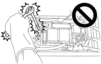
When troubleshooting DTC P0AA649, use either a tool wrapped with vinyl insulation tape or an insulated tool. (It is extremely dangerous when a high-voltage charge passes through a non-insulated tool causing a short.)
- NOTICE:
-
When using a megohmmeter set to 500 V to measure resistance, adhere to the following precautions.
- ·
Use a direct current(DC) resistance tester capable of measuring resistances of 100 MΩ or higher at DC 500 V when measuring resistance.
Do not use an alternating current(AC) resistance tester for this check as the correct measurement cannot be taken.
·After DC 500 V is applied and insulation resistance value has stabilized, read the measured value.
Time is needed for the insulation resistance value to stabilize. If a measurement value is read before it has stabilized, the correct measurement cannot be taken.
- HINT:
-
When measuring insulation resistance using a megohmmeter, set the megohmmeter to 500 V.
PROCEDURE
Connect the GTS to the DLC3.
Turn the power switch on (IG).
Enter the following menus: Powertrain / Hybrid Control and HV Battery / Trouble Codes.
Check for DTCs.
- Powertrain > Hybrid Control > Trouble Codes
- 50001 397
- Powertrain > HV Battery > Trouble Codes
- 50001 398
- Result:
Result Proceed to P0AA649, P1C7C49, P1C7D49, P1C7E49, P1C7F49 or P1C8049 only is output, or DTCs except the ones in the table below are also output. A DTCs of hybrid control system in the tables below are output. B DTCs of hybrid battery system in the tables below are output. C
| Malfunction Content | System | Relevant DTC | |
|---|---|---|---|
| Microcomputer malfunction | Hybrid control system | P060647 | Hybrid/EV Powertrain Control Module Processor Watchdog / Safety MCU Failure |
| P060A29 | Hybrid/EV Powertrain Control Module Monitoring Processor Signal Invalid | ||
| P060A44 | Hybrid/EV Powertrain Control Module Monitoring Processor Data Memory Failure | ||
| P060A45 | Hybrid/EV Powertrain Control Module Monitoring Processor Program Memory Failure | ||
| P060A49 | Hybrid/EV Powertrain Control Module Monitoring Processor Internal Electronic Failure | ||
| P060B1C | Hybrid/EV Powertrain Control Module A/D Processing Voltage Out of Range | ||
| P060B71 | Hybrid/EV Powertrain Control Module A/D Processing Actuator Stuck | ||
| P1CE31C | Hybrid/EV Powertrain Control Module Monitoring Processor A/D Processing Voltage Out of Range | ||
| P1CE349 | Hybrid/EV Powertrain Control Module Monitoring Processor A/D Processing Internal Electronic Failure | ||
| P1CE371 | Hybrid/EV Powertrain Control Module Monitoring Processor A/D Processing Actuator Stuck | ||
| Hybrid battery system | P060687 | Hybrid/EV Battery Energy Control Module Processor to Monitoring Processor Missing Message | |
| P060A47 | Hybrid/EV Battery Energy Control Module Monitoring Processor Watchdog / Safety MCU Failure | ||
| P060A87 | Hybrid/EV Battery Energy Control Module Processor from Monitoring Processor Missing Message | ||
| P060B49 | Hybrid/EV Powertrain Control Module A/D Processing Internal Electronic Failure | ||
| P062F46 | Hybrid/EV Battery Energy Control Module EEPROM Calibration / Parameter Memory Failure | ||
| Power Source Circuit Malfunction | Hybrid control system | P06881F | ECM/PCM Power Relay Sense Circuit Intermittent |
| System malfunction | Hybrid control system | P1C9E9F | Hybrid/EV System Reset Stuck Off |
- HINT:
- ·
P0AA649 may be output as a result of the malfunction indicated by the DTCs above.
(a)The chart above is listed in inspection order of priority.
(b)Check DTCs that are output at the same time by following the listed order. (The main cause of the malfunction can be determined without performing unnecessary inspections.)
Turn the power switch off.
A
B
C
Connect the GTS to the DLC3.
Turn the power switch on (IG).
Enter the following menus: Powertrain / Hybrid Control / Trouble Codes.
Check for DTCs.
- Powertrain > Hybrid Control > Trouble Codes
- 50001 397
- NOTICE:
- ·
DTC P1C7C49, P1C7D49, P1C7E49, P1C7F49 and P1C8049 are not stored with P0AA649 at the same time. If a drop in insulation resistance is detected and DTC P0AA649 is output, wait for 1 minute with the power switch on (READY), the shift lever in D and the air conditioning system on within the same trip, then turn the power switch off and wait for 2 minutes to determine the DTC (P1C7C49, P1C7D49, P1C7E49, P1C7F49 or P1C8049).
·If only DTC P0AA649 is output, perform the diagnostic procedure for DTC P0AA649 to inspect all of the high voltage circuits.
·When any other DTC indicating parts which the insulation resistance dropped are output, perform the diagnostic procedure for each DTC.
- Result:
Result Proceed to P0AA649 (decrease in the insulation resistance of the high-voltage circuit) only is output. A P0AA649 and P1C7C49 (decrease in the insulation resistance of the air conditioning system area) are output. B P0AA649 and P1C7D49 (decrease in the insulation resistance of the HV battery area) are output. C P0AA649 and P1C7E49 (decrease in the insulation resistance of the hybrid vehicle transaxle assembly area) are output. D P0AA649 and P1C7F49 (decrease in the insulation resistance of the high-voltage direct current area) are output. E P0AA649 and P1C8049 (decrease in the insulation resistance of the rear motor area) are output. F
Turn the power switch off.
A
B
C
D
E
F
- CAUTION:
-
Be sure to wear insulated gloves.
Check that the service plug grip is not installed.
- NOTICE:
-
After removing the service plug grip, do not turn the power switch on (READY), unless instructed by the repair manual because this may cause a malfunction.
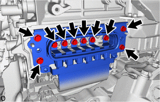
Disconnect the motor cable from the inverter with converter assembly.
- HINT:
-
Make sure that no foreign matter, coolant or water enters the inverter with converter assembly.
Connect the cable to the negative (-) auxiliary battery terminal.
Turn the power switch on (IG).
- NOTICE:
-
Turning the power switch on (IG) with the service plug grip removed causes DTCs to be stored. Clear the DTCs after performing this inspection.
Move the shift lever to N and lift the vehicle.
Turn the power switch off.
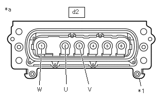
| *1 | Shield Ground |
| *a | Motor Cable (for MG2)
(Inverter with Converter Assembly Side) |
Using a megohmmeter set to 500 V, measure the resistance according to the value(s) in the table below while rotating the front wheels 2 revolutions in the same direction simultaneously.
- NOTICE:
- ·
Carefully perform this inspection as the motor (MG2) may generate current when the front wheels are rotated by hand.
·Be sure to set the megohmmeter to 500 V when performing this test. Using a setting higher than 500 V can result in damage to the component being inspected.
- HINT:
-
As the insulation resistance may vary when motor (MG2) rotates, perform this inspection while rotating the front wheels.
- Standard Resistance:
Tester Connection Condition Specified Condition d2-2 (U) - Body ground and shield ground Power switch off 10 MΩ or higher d2-3 (V) - Body ground and shield ground Power switch off 10 MΩ or higher d2-1 (W) - Body ground and shield ground Power switch off 10 MΩ or higher
Lower the vehicle and move the shift lever to P.
Disconnect the cable from the negative (-) auxiliary battery terminal.
- Result:
Proceed to OK NG
OK
NG
- CAUTION:
-
Be sure to wear insulated gloves.
Check that the service plug grip is not installed.
- NOTICE:
-
After removing the service plug grip, do not turn the power switch on (READY), unless instructed by the repair manual because this may cause a malfunction.
Connect the cable to the negative (-) auxiliary battery terminal.
Turn the power switch on (IG).
- NOTICE:
-
Turning the power switch on (IG) with the service plug grip removed causes DTCs to be stored. Clear the DTCs after performing this inspection.
Move the shift lever to N and lift the vehicle.
Turn the power switch off.

| *1 | Shield Ground |
| *a | Motor Cable (for MG1)
(Inverter with Converter Assembly Side) |
Using a megohmmeter set to 500 V, measure the resistance according to the value(s) in the table below while rotating the front wheels 2 revolutions in the same direction simultaneously.
- NOTICE:
- ·
Carefully perform this inspection as the generator (MG1) may generate current when the front wheels are rotated by hand.
·Be sure to set the megohmmeter to 500 V when performing this test. Using a setting higher than 500 V can result in damage to the component being inspected.
- HINT:
-
As the insulation resistance may vary when generator (MG1) rotates, perform this inspection while rotating the front wheels.
- Standard Resistance:
Tester Connection Condition Specified Condition d2-5 (U) - Body ground and shield ground Power switch off 10 MΩ or higher d2-6 (V) - Body ground and shield ground Power switch off 10 MΩ or higher d2-4 (W) - Body ground and shield ground Power switch off 10 MΩ or higher
Lower the vehicle and move the shift lever to P.
Disconnect the cable from the negative (-) auxiliary battery terminal.
- Result:
Proceed to OK NG
OK
NG
- Result:
Result Proceed to for 2WD A for AWD B
A
B
- CAUTION:
-
Be sure to wear insulated gloves.
Check that the service plug grip is not installed.
- NOTICE:
-
After removing the service plug grip, do not turn the power switch on (READY), unless instructed by the repair manual because this may cause a malfunction.
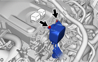
Disconnect the HV air conditioning wire connector from the inverter with converter assembly.
- HINT:
-
Make sure that no foreign matter has entered or contaminated the HV air conditioning wire.
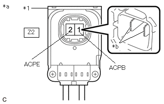
| *1 | Shield Ground |
| *a | HV Air Conditioning Wire
(Inverter with Converter Assembly Side) |
| *b | Tip of Terminal |
Using a megohmmeter set to 500 V, measure the resistance according to the value(s) in the table below.
- NOTICE:
- ·
Be sure to set the megohmmeter to 500 V when performing this test. Using a setting higher than 500 V can result in damage to the component being inspected.
·Be sure to inspect with connecting the tester probes to the tips of the terminal.
- Standard Resistance:
Tester Connection Condition Specified Condition Z2-1 (ACPB) - Body ground and shield ground Power switch off 3 MΩ or higher Z2-2 (ACPE) - Body ground and shield ground Power switch off 3 MΩ or higher
- Result:
Proceed to OK NG
OK
NG
- CAUTION:
-
Be sure to wear insulated gloves.
Check that the service plug grip is not installed.
- NOTICE:
-
After removing the service plug grip, do not turn the power switch on (READY), unless instructed by the repair manual because this may cause a malfunction.
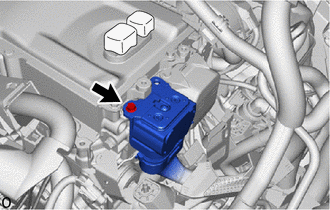
Disconnect the floor under wire connector from the inverter with converter assembly.
- HINT:
-
Make sure that no foreign matter has entered or contaminated the floor under wire.
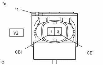
| *1 | Shield Ground |
| *a | Floor under wire
(Inverter with Converter Assembly Side) |
for 2WD:
Using a megohmmeter set to 500 V, measure the resistance according to the value(s) in the table below.
- NOTICE:
- ·
Be sure to set the megohmmeter to 500 V when performing this test. Using a setting higher than 500 V can result in damage to the component being inspected.
·Be sure not to damage or deform the terminal being inspected.
- Standard Resistance:
Tester Connection Condition Specified Condition Y2-1 (CBI) - Body ground and shield ground Power switch off 10 MΩ or higher Y2-2 (CEI) - Body ground and shield ground Power switch off 10 MΩ or higher
- HINT:
-
Visually inspect the floor under wire for damage. If there is any damage, then this is the likely cause of low insulation resistance.
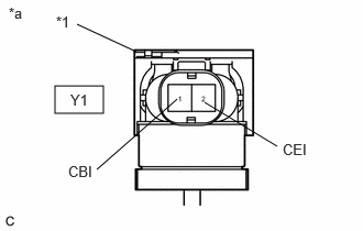
| *1 | Shield Ground |
| *a | Floor under wire
(Inverter with Converter Assembly Side) |
for AWD:
Using a megohmmeter set to 500 V, measure the resistance according to the value(s) in the table below.
- NOTICE:
- ·
Be sure to set the megohmmeter to 500 V when performing this test. Using a setting higher than 500 V can result in damage to the component being inspected.
·Be sure not to damage or deform the terminal being inspected.
- Standard Resistance:
Tester Connection Condition Specified Condition Y1-1 (CBI) - Body ground and shield ground Power switch off 10 MΩ or higher Y1-2 (CEI) - Body ground and shield ground Power switch off 10 MΩ or higher
- HINT:
-
Visually inspect the floor under wire for damage. If there is any damage, then this is the likely cause of low insulation resistance.
- Result:
Proceed to OK NG
OK
NG
- CAUTION:
-
Be sure to wear insulated gloves.
Check that the service plug grip is not installed.
- NOTICE:
-
After removing the service plug grip, do not turn the power switch on (READY), unless instructed by the repair manual because this may cause a malfunction.
Connect the floor under wire connector to the inverter with converter assembly.
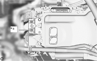
| *a | High Voltage Terminal |
Using a megohmmeter set to 500 V, measure the resistance according to the value(s) in the table below.
- NOTICE:
-
Be sure to set the megohmmeter to 500 V when performing this test. Using a setting higher than 500 V can result in damage to the component being inspected.
- Standard Resistance:
Tester Connection Condition Specified Condition High voltage terminal - Body ground Power switch off 1 MΩ or higher
- HINT:
-
Perform this inspection with the motor cable, floor under wire and air conditioning wire disconnected from the inverter with converter assembly.
- Result:
Proceed to OK NG
OK
NG
- CAUTION:
-
Be sure to wear insulated gloves and protective goggles.
- HINT:
-
Make sure that no foreign matter or water has entered the HV battery.
Check that the service plug grip is not installed.
- NOTICE:
-
After removing the service plug grip, do not turn the power switch on (READY), unless instructed by the repair manual because this may cause a malfunction.
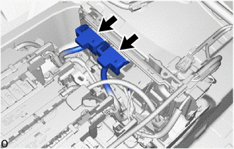
Disconnect the battery ECU assembly connectors.
- NOTICE:
-
Insulate each disconnected high-voltage connector with insulating tape. Wrap the connector from the wire harness side to the end of the connector.
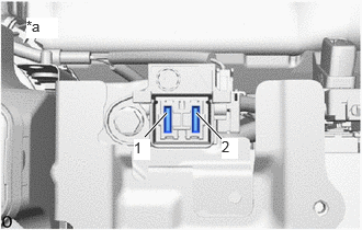
| *a | Service Plug Grip Removed
(Service Plug Grip Connecting Terminals) |
Using a megohmmeter set to 500 V, measure the resistance according to the value(s) in the table below.
- NOTICE:
-
Be sure to set the megohmmeter to 500 V when performing this test. Using a setting higher than 500 V can result in damage to the component being inspected.
- Standard Resistance:
Tester Connection Condition Specified Condition 1 - Body ground Power switch off 10 MΩ or higher 2 - Body ground Power switch off 10 MΩ or higher
- Result:
Proceed to OK NG
OK
NG
- Result:
Proceed to NEXT
NEXT
- CAUTION:
-
Be sure to wear insulated gloves.
Check that the service plug grip is not installed.
- NOTICE:
-
After removing the service plug grip, do not turn the power switch on (READY), unless instructed by the repair manual because this may cause a malfunction.
Remove the motor cable from the hybrid vehicle transaxle assembly.
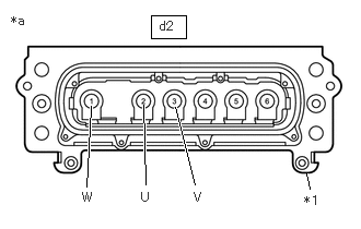
| *1 | Shield Ground |
| *a | Motor Cable (for MG2)
(Inverter with Converter Assembly Side) |
Using a megohmmeter set to 500 V, measure the resistance according to the value(s) in the table below.
- NOTICE:
-
Be sure to set the megohmmeter to 500 V when performing this test. Using a setting higher than 500 V can result in damage to the component being inspected.
- Standard Resistance:
Tester Connection Condition Specified Condition d2-2 (U) - Shield ground Power switch off 10 MΩ or higher d2-3 (V) - Shield ground Power switch off 10 MΩ or higher d2-1 (W) - Shield ground Power switch off 10 MΩ or higher
- Result:
Proceed to OK NG
OK
NG
- CAUTION:
-
Be sure to wear insulated gloves.
Check that the service plug grip is not installed.
- NOTICE:
-
After removing the service plug grip, do not turn the power switch on (READY), unless instructed by the repair manual because this may cause a malfunction.
Remove the motor cable from the hybrid vehicle transaxle assembly.
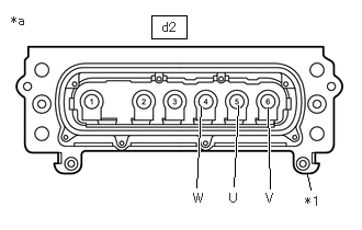
| *1 | Shield Ground |
| *a | Motor Cable (for MG1)
(Inverter with Converter Assembly Side) |
Using a megohmmeter set to 500 V, measure the resistance according to the value(s) in the table below.
- NOTICE:
-
Be sure to set the megohmmeter to 500 V when performing this test. Using a setting higher than 500 V can result in damage to the component being inspected.
- Standard Resistance:
Tester Connection Condition Specified Condition d2-5 (U) - Shield ground Power switch off 10 MΩ or higher d2-6 (V) - Shield ground Power switch off 10 MΩ or higher d2-4 (W) - Shield ground Power switch off 10 MΩ or higher
- Result:
Proceed to OK NG
OK
NG
- CAUTION:
-
Be sure to wear insulated gloves and protective goggles.
Check that the service plug grip is not installed.
- NOTICE:
-
After removing the service plug grip, do not turn the power switch on (READY), unless instructed by the repair manual because this may cause a malfunction.
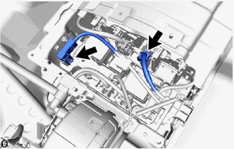
Disconnect the electric vehicle battery plug assembly connectors.
| *a | Service Plug Grip Removed
(Service Plug Grip Connecting Terminals) |
Using a megohmmeter set to 500 V, measure the resistance according to the value(s) in the table below.
- NOTICE:
-
Be sure to set the megohmmeter to 500 V when performing this test. Using a setting higher than 500 V can result in damage to the component being inspected.
- Standard Resistance:
Tester Connection Condition Specified Condition 1 - Body ground Power switch off 10 MΩ or higher 2 - Body ground Power switch off 10 MΩ or higher
- Result:
Proceed to OK NG
OK
NG
- CAUTION:
-
Be sure to wear insulated gloves.
Check that the service plug grip is not installed.
- NOTICE:
-
After removing the service plug grip, do not turn the power switch on (READY), unless instructed by the repair manual because this may cause a malfunction.
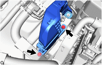
Disconnect the floor under wire (rear traction motor cable) from the inverter with converter assembly.
- HINT:
-
Make sure that no foreign matter, coolant or water enters the inverter with converter assembly.
Connect the cable to the negative (-) auxiliary battery terminal.
Turn the power switch on (IG).
- NOTICE:
-
Turning the power switch on (IG) with the service plug grip removed causes DTCs to be stored. Clear the DTCs after performing this inspection.
Move the shift lever to N and lift the vehicle.
Turn the power switch off.
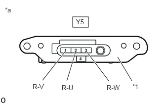
| *1 | Shield Ground |
| *a | Floor Under Wire (Rear Traction Motor Cable)
(Inverter with Converter Assembly Side) |
Using a megohmmeter set to 500 V, measure the resistance according to the value(s) in the table below while rotating the rear wheels 2 revolutions in the same direction simultaneously.
- NOTICE:
- ·
Carefully perform this inspection as the rear motor (MGR) may generate current when the rear wheels are rotated by hand.
·Be sure to set the megohmmeter to 500 V when performing this test. Using a setting higher than 500 V can result in damage to the component being inspected.
- HINT:
-
As the insulation resistance may vary when rear motor (MGR) rotates, perform this inspection while rotating the rear wheels.
- Standard Resistance:
Tester Connection Condition Specified Condition Y5-2 (R-U) - Body ground and shield ground Power switch off 100 MΩ or higher Y5-1 (R-V) - Body ground and shield ground Power switch off 100 MΩ or higher Y5-3 (R-W) - Body ground and shield ground Power switch off 100 MΩ or higher
Lower the vehicle and move the shift lever to P.
Disconnect the cable from the negative (-) auxiliary battery terminal.
- Result:
Proceed to OK NG
OK
NG
- Result:
Proceed to NEXT
NEXT
Check that no types of compressor oil other than ND-OIL 11 (such as ND-OIL 8, etc.) were used in the past.
- HINT:
- ·
Electrical insulation performance may decrease significantly if even a small amount of oil other than ND-OIL 11 is used (or enters) in the refrigerant cycle, causing a DTC to be output.
·Replace the main components of the refrigerant cycle (No. 1 cooler evaporator sub-assembly, cooler condenser assembly, compressor with motor assembly, No. 1 expansion valve, and piping) if a large amount of oil other than ND-OIL 11 enters the system. Failing to do so may cause electrical insulation performance to remain low, causing a DTC to be stored.
- Result:
Proceed to OK NG
OK
for A25B-FXS:
for A25D-FXS:
for A25F-FXS:
NG
- CAUTION:
-
Be sure to wear insulated gloves.
Check that the service plug grip is not installed.
- NOTICE:
-
After removing the service plug grip, do not turn the power switch on (READY), unless instructed by the repair manual because this may cause a malfunction.
Remove the (rear traction motor cable) from the rear traction motor with transaxle assembly.
| *1 | Shield Ground |
| *a | Floor Under Wire (Rear Traction Motor Cable)
(Inverter with Converter Assembly Side) |
Using a megohmmeter set to 500 V, measure the resistance according to the value(s) in the table below.
- NOTICE:
-
Be sure to set the megohmmeter to 500 V when performing this test. Using a setting higher than 500 V can result in damage to the component being inspected.
- Standard Resistance:
Tester Connection Condition Specified Condition Y5-2 (R-U) - Shield ground Power switch off 10 MΩ or higher Y5-1 (R-V) - Shield ground Power switch off 10 MΩ or higher Y5-3 (R-W) - Shield ground Power switch off 10 MΩ or higher
- Result:
Proceed to OK NG
OK
NG
- CAUTION:
-
Be sure to wear insulated gloves and protective goggles.
Check that the service plug grip is not installed.
- NOTICE:
-
After removing the service plug grip, do not turn the power switch on (READY), unless instructed by the repair manual because this may cause a malfunction.
Remove the electric vehicle battery plug assembly.
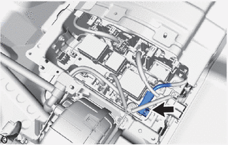
Disconnect the high voltage cable connector of the HV battery from the HV battery junction block assembly.
- NOTICE:
-
Insulate each disconnected high-voltage connector with insulating tape. Wrap the connector from the wire harness side to the end of the connector.
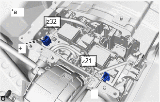
| *a | Component without harness connected
(HV Battery Junction Block Assembly) |
Using a megohmmeter set to 500 V, measure the resistance according to the value(s) in the table below.
- NOTICE:
-
Be sure to set the megohmmeter to 500 V when performing this test. Using a setting higher than 500 V can result in damage to the component being inspected.
- Standard Resistance:
Tester Connection Condition Specified Condition z32-1 (+) - Body ground Power switch off 10 MΩ or higher z21-1 (-) - Body ground Power switch off 10 MΩ or higher
- Result:
Proceed to OK NG
OK
NG
- CAUTION:
-
Be sure to wear insulated gloves and protective goggles.
Check that the service plug grip is not installed.
- NOTICE:
-
After removing the service plug grip, do not turn the power switch on (READY), unless instructed by the repair manual because this may cause a malfunction.
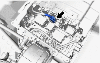
Disconnect the high voltage cable connector of the HV battery from the hybrid battery terminal block.
- NOTICE:
-
Insulate each disconnected high-voltage connector with insulating tape. Wrap the connector from the wire harness side to the end of the connector.
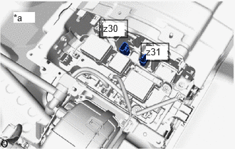
| *a | Component without harness connected
(Hybrid Battery Terminal Block) |
Using a megohmmeter set to 500 V, measure the resistance according to the value(s) in the table below.
- NOTICE:
-
Be sure to set the megohmmeter to 500 V when performing this test. Using a setting higher than 500 V can result in damage to the component being inspected.
- Standard Resistance:
Tester Connection Condition Specified Condition z31-1 - Body ground Power switch off 10 MΩ or higher z30-1 - Body ground Power switch off 10 MΩ or higher
- Result:
Proceed to OK NG
OK
NG
- CAUTION:
-
Be sure to wear insulated gloves and protective goggles.
Check that no electrolyte is leaking from each HV supply stack sub-assembly.
- Result:
Result Proceed to Electrolyte is not leaking from the HV supply stack sub-assembly. A Electrolyte is leaking from the HV supply stack sub-assembly. B
A
B
- CAUTION:
-
Be sure to wear insulated gloves and protective goggles.
Check that the service plug grip is not installed.
- NOTICE:
-
After removing the service plug grip, do not turn the power switch on (READY), unless instructed by the repair manual because this may cause a malfunction.
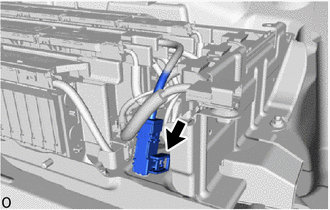
Disconnect the HV battery high voltage connector.
- NOTICE:
-
Insulate each disconnected high-voltage connector with insulating tape. Wrap the connector from the wire harness side to the end of the connector.
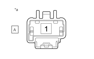
| *a | Component without harness connected
(No. 2 HV Supply Stack Sub-assembly) |
Using a megohmmeter set to 500 V, measure the resistance according to the value(s) in the table below.
- NOTICE:
-
Be sure to set the megohmmeter to 500 V when performing this test. Using a setting higher than 500 V can result in damage to the component being inspected.
- Standard Resistance:
Tester Connection Condition Specified Condition A-1 - Body ground Power switch off 10 MΩ or higher
- Result:
Proceed to OK NG
OK
NG
- Result:
Proceed to NEXT
NEXT
- Result:
Proceed to NEXT
NEXT
- Result:
Proceed to NEXT
NEXT
- Result:
Proceed to NEXT
NEXT
- CAUTION:
-
Be sure to wear insulated gloves.
Check that the service plug grip is not installed.
- NOTICE:
-
After removing the service plug grip, do not turn the power switch on (READY), unless instructed by the repair manual because this may cause a malfunction.
Disconnect the motor cable from the inverter with converter assembly.
- HINT:
-
Make sure that no foreign matter, coolant or water enters the inverter with converter assembly.
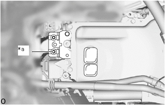
| *a | High Voltage Terminal |
Using a megohmmeter set to 500 V, measure the resistance according to the value(s) in the table below.
- NOTICE:
-
Be sure to set the megohmmeter to 500 V when performing this test. Using a setting higher than 500 V can result in damage to the component being inspected.
- Standard Resistance:
Tester Connection Condition Specified Condition High voltage terminal - Body ground Power switch off 1 MΩ or higher
- HINT:
-
Perform this inspection with the motor cable disconnected from the inverter with converter assembly.
- Result:
Proceed to OK NG
OK
NG
- CAUTION:
-
Be sure to wear insulated gloves.
Check that the service plug grip is not installed.
- NOTICE:
-
After removing the service plug grip, do not turn the power switch on (READY), unless instructed by the repair manual because this may cause a malfunction.
Remove the motor cable from the hybrid vehicle transaxle assembly.
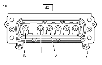
| *1 | Shield Ground |
| *a | Motor Cable (for MG2)
(Inverter with Converter Assembly Side) |
Using a megohmmeter set to 500 V, measure the resistance according to the value(s) in the table below.
- NOTICE:
-
Be sure to set the megohmmeter to 500 V when performing this test. Using a setting higher than 500 V can result in damage to the component being inspected.
- Standard Resistance:
Tester Connection Condition Specified Condition d2-2 (U) - Shield ground Power switch off 10 MΩ or higher d2-3 (V) - Shield ground Power switch off 10 MΩ or higher d2-1 (W) - Shield ground Power switch off 10 MΩ or higher
- Result:
Proceed to OK NG
OK
NG
- CAUTION:
-
Be sure to wear insulated gloves.
Check that the service plug grip is not installed.
- NOTICE:
-
After removing the service plug grip, do not turn the power switch on (READY), unless instructed by the repair manual because this may cause a malfunction.
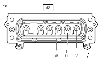
| *1 | Shield Ground |
| *a | Motor Cable (for MG1)
(Inverter with Converter Assembly Side) |
Using a megohmmeter set to 500 V, measure the resistance according to the value(s) in the table below.
- NOTICE:
-
Be sure to set the megohmmeter to 500 V when performing this test. Using a setting higher than 500 V can result in damage to the component being inspected.
- Standard Resistance:
Tester Connection Condition Specified Condition d2-5 (U) - Shield ground Power switch off 10 MΩ or higher d2-6 (V) - Shield ground Power switch off 10 MΩ or higher d2-4 (W) - Shield ground Power switch off 10 MΩ or higher
- Result:
Proceed to OK NG
OK
NG
- Result:
Proceed to NEXT
NEXT
- Result:
Proceed to NEXT
NEXT
- Result:
Proceed to NEXT
NEXT
- CAUTION:
-
Be sure to wear insulated gloves.
Check that the service plug grip is not installed.
- NOTICE:
-
After removing the service plug grip, do not turn the power switch on (READY), unless instructed by the repair manual because this may cause a malfunction.
Disconnect the floor under wire connector from the inverter with converter assembly.
- HINT:
-
Make sure that no foreign matter has entered or contaminated the floor under wire.
| *1 | Shield Ground |
| *a | Floor under wire
(Inverter with Converter Assembly Side) |
for 2WD:
Using a megohmmeter set to 500 V, measure the resistance according to the value(s) in the table below.
- NOTICE:
- ·
Be sure to set the megohmmeter to 500 V when performing this test. Using a setting higher than 500 V can result in damage to the component being inspected.
·Be sure not to damage or deform the terminal being inspected.
- Standard Resistance:
Tester Connection Condition Specified Condition Y2-1 (CBI) - Body ground and shield ground Power switch off 10 MΩ or higher Y2-2 (CEI) - Body ground and shield ground Power switch off 10 MΩ or higher
- HINT:
-
Visually inspect the floor under wire for damage. If there is any damage, then this is the likely cause of low insulation resistance.
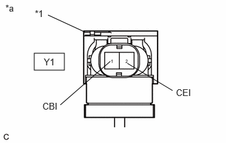
| *1 | Shield Ground |
| *a | Floor under wire
(Inverter with Converter Assembly Side) |
for AWD:
Using a megohmmeter set to 500 V, measure the resistance according to the value(s) in the table below.
- NOTICE:
- ·
Be sure to set the megohmmeter to 500 V when performing this test. Using a setting higher than 500 V can result in damage to the component being inspected.
·Be sure not to damage or deform the terminal being inspected.
- Standard Resistance:
Tester Connection Condition Specified Condition Y1-1 (CBI) - Body ground and shield ground Power switch off 10 MΩ or higher Y1-2 (CEI) - Body ground and shield ground Power switch off 10 MΩ or higher
- HINT:
-
Visually inspect the floor under wire for damage. If there is any damage, then this is the likely cause of low insulation resistance.
- Result:
Proceed to OK NG
OK
NG
- CAUTION:
-
Be sure to wear insulated gloves.
Check that the service plug grip is not installed.
- NOTICE:
-
After removing the service plug grip, do not turn the power switch on (READY), unless instructed by the repair manual because this may cause a malfunction.
Disconnect the HV air conditioning wire connector from the inverter with converter assembly.
- HINT:
-
Make sure that no foreign matter has entered or contaminated the HV air conditioning wire.
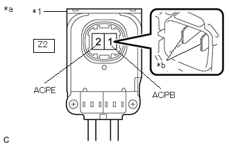
| *1 | Shield Ground |
| *a | HV Air Conditioning Wire
(Inverter with Converter Assembly Side) |
| *b | Tip of Terminal |
Using a megohmmeter set to 500 V, measure the resistance according to the value(s) in the table below.
- NOTICE:
- ·
Be sure to set the megohmmeter to 500 V when performing this test. Using a setting higher than 500 V can result in damage to the component being inspected.
·Be sure to inspect with connecting the tester probes to the tips of the terminal.
- Standard Resistance:
Tester Connection Condition Specified Condition Z2-1 (ACPB) - Body ground and shield ground Power switch off 3 MΩ or higher Z2-2 (ACPE) - Body ground and shield ground Power switch off 3 MΩ or higher
- Result:
Proceed to OK NG
OK
NG
for 2WD:
for AWD:
- Result:
Proceed to NEXT
NEXT
- CAUTION:
-
Be sure to wear insulated gloves.
Check that the service plug grip is not installed.
- NOTICE:
-
After removing the service plug grip, do not turn the power switch on (READY), unless instructed by the repair manual because this may cause a malfunction.
Remove the No. 1 HV battery cover panel RH.
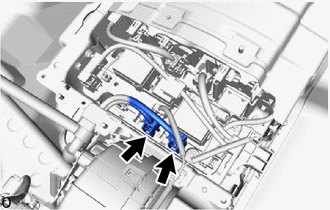
Disconnect the floor under wire connectors from the HV battery junction block assembly.
- HINT:
-
Make sure that no foreign matter has entered or contaminated the floor under wire.
| *1 | Shield Ground |
| *a | Floor under wire
(Inverter with Converter Assembly Side) |
for 2WD:
Using a megohmmeter set to 500 V, measure the resistance according to the value(s) in the table below.
- NOTICE:
- ·
Be sure to set the megohmmeter to 500 V when performing this test. Using a setting higher than 500 V can result in damage to the component being inspected.
·Be sure not to damage or deform the terminal being inspected.
- Standard Resistance:
Tester Connection Condition Specified Condition Y2-1 (CBI) - Body ground and shield ground Power switch off 10 MΩ or higher Y2-2 (CEI) - Body ground and shield ground Power switch off 10 MΩ or higher
- HINT:
-
Visually inspect the floor under wire for damage. If there is any damage, then this is the likely cause of low insulation resistance.
| *1 | Shield Ground |
| *a | Floor under wire
(Inverter with Converter Assembly Side) |
for AWD:
Using a megohmmeter set to 500 V, measure the resistance according to the value(s) in the table below.
- NOTICE:
- ·
Be sure to set the megohmmeter to 500 V when performing this test. Using a setting higher than 500 V can result in damage to the component being inspected.
·Be sure not to damage or deform the terminal being inspected.
- Standard Resistance:
Tester Connection Condition Specified Condition Y1-1 (CBI) - Body ground and shield ground Power switch off 10 MΩ or higher Y1-2 (CEI) - Body ground and shield ground Power switch off 10 MΩ or higher
- HINT:
-
Visually inspect the floor under wire for damage. If there is any damage, then this is the likely cause of low insulation resistance.
- Result:
Proceed to OK NG
OK
NG
- Result:
Proceed to NEXT
NEXT
- CAUTION:
-
Be sure to wear insulated gloves.
Check that the service plug grip is not installed.
- NOTICE:
-
After removing the service plug grip, do not turn the power switch on (READY), unless instructed by the repair manual because this may cause a malfunction.
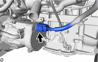
Disconnect the HV air conditioning wire from the compressor with motor assembly.
for A25B-FXS: Click hereVehicle Interior>HEATING / AIR CONDITIONING>COMPRESSOR (for A25B-FXS)>REMOVAL202409,999999,_58,_083104,_0403068,RM100000002NFZN,
for A25D-FXS: Click hereVehicle Interior>HEATING / AIR CONDITIONING>COMPRESSOR (for A25D-FXS)>REMOVAL202409,999999,_58,_083104,_0476991,RM100000002NHZX,
for A25F-FXS: Click hereVehicle Interior>HEATING / AIR CONDITIONING>COMPRESSOR (for A25F-FXS [Production date from 2021/08])>REMOVAL202409,999999,_58,_083104,_0482692,RM100000002NHZV,
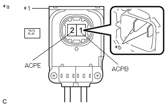
| *1 | Shield Ground |
| *a | HV Air Conditioning Wire
(Inverter with Converter Assembly Side) |
| *b | Tip of Terminal |
Using a megohmmeter set to 500 V, measure the resistance according to the value(s) in the table below.
- NOTICE:
- ·
Be sure to set the megohmmeter to 500 V when performing this test. Using a setting higher than 500 V can result in damage to the component being inspected.
·Be sure to inspect with connecting the tester probes to the tips of the terminal.
- Standard Resistance:
Tester Connection Condition Specified Condition Z2-1 (ACPB) - Body ground and shield ground Power switch off 10 MΩ or higher Z2-2 (ACPE) - Body ground and shield ground Power switch off 10 MΩ or higher
- Result:
Proceed to OK NG
OK
NG
for A25B-FXS:
for A25D-FXS:
for A25F-FXS:
- Result:
Proceed to NEXT
NEXT
- Result:
Proceed to NEXT
NEXT
- Result:
Proceed to NEXT
NEXT
- CAUTION:
-
Be sure to wear insulated gloves.
Check that the service plug grip is not installed.
- NOTICE:
-
After removing the service plug grip, do not turn the power switch on (READY), unless instructed by the repair manual because this may cause a malfunction.
Disconnect the floor under wire (rear traction motor cable) from the inverter with converter assembly.
- HINT:
-
Make sure that no foreign matter, coolant or water enters the inverter with converter assembly.
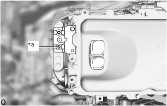
| *a | High Voltage Terminal |
Using a megohmmeter set to 500 V, measure the resistance according to the value(s) in the table below.
- NOTICE:
-
Be sure to set the megohmmeter to 500 V when performing this test. Using a setting higher than 500 V can result in damage to the component being inspected.
- Standard Resistance:
Tester Connection Condition Specified Condition High voltage terminal - Body ground Power switch off 1 MΩ or higher
- HINT:
-
Perform this inspection with the floor under wire (rear traction motor cable) disconnected from the inverter with converter assembly.
- Result:
Proceed to OK NG
OK
NG
- CAUTION:
-
Be sure to wear insulated gloves.
Check that the service plug grip is not installed.
- NOTICE:
-
After removing the service plug grip, do not turn the power switch on (READY), unless instructed by the repair manual because this may cause a malfunction.

Remove the floor under wire (rear traction motor cable) from the rear traction motor with transaxle assembly.
| *1 | Shield Ground |
| *a | Floor under wire (Rear Traction Motor Cable)
(Inverter with Converter Assembly Side) |
Using a megohmmeter set to 500 V, measure the resistance according to the value(s) in the table below.
- NOTICE:
-
Be sure to set the megohmmeter to 500 V when performing this test. Using a setting higher than 500 V can result in damage to the component being inspected.
- Standard Resistance:
Tester Connection Condition Specified Condition Y5-2 (R-U) - Shield ground Power switch off 10 MΩ or higher Y5-1 (R-V) - Shield ground Power switch off 10 MΩ or higher Y5-3 (R-W) - Shield ground Power switch off 10 MΩ or higher
- Result:
Proceed to OK NG
OK
NG
- CAUTION:
-
Be sure to wear insulated gloves.
Check that the service plug grip is not installed.
- NOTICE:
-
After removing the service plug grip, do not turn the power switch on (READY), unless instructed by the repair manual because this may cause a malfunction.
Remove the rear traction motor cable from the rear traction motor with transaxle assembly.
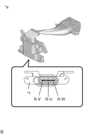
| *1 | Shield Ground |
| *a | Rear Traction Motor Cable |
Using a megohmmeter set to 500 V, measure the resistance according to the value(s) in the table below.
- NOTICE:
-
Be sure to set the megohmmeter to 500 V when performing this test. Using a setting higher than 500 V can result in damage to the component being inspected.
- Standard Resistance:
Tester Connection Condition Specified Condition R-W - Shield ground Ignition switch off 100 MΩ or higher R-V - Shield ground Ignition switch off 100 MΩ or higher R-U - Shield ground Ignition switch off 100 MΩ or higher
Install the rear traction motor cable.
- Result:
Proceed to OK NG
OK
NG
- Result:
Proceed to NEXT
NEXT
- Result:
Proceed to NEXT
NEXT
- Result:
Proceed to NEXT
NEXT