EXTERIOR PANELS / TRIM BLACK OUT TAPE(for Rear Door) INSTALLATION
CAUTION / NOTICE / HINT
- HINT:
- ·
Use the same procedure for the RH and LH sides.
·The procedure listed below is for the LH side.
PROCEDURE

 1. REPAIR INSTRUCTION
75954A
2.INSTALL REAR INNER BLACK OUT TAPE LH
Refer to the illustration to position a new rear inner black out tape LH.
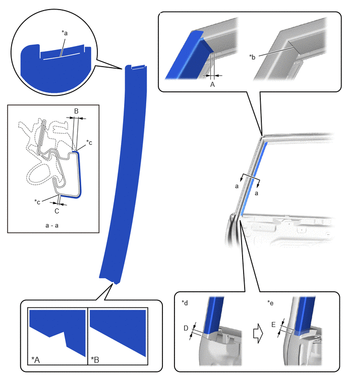
| *A | for RH Side | *B | for LH Side |
| *a | Point A | *b | Point B |
| *c | Edge of Curved Surface | *d | When removing Rear Door Weatherstrip LH |
| *e | When installing Rear Door Weatherstrip LH | - | - |
- Standard Measurement:
Area Measurement Area Measurement A 4.0 mm (0.157 in.) B 1.6 to 3.6 mm (0.0629 to 0.142 in.) C 1.0 mm (0.0393 in.) D 5.5 mm (0.216 in.) E 5.0 mm (0.216 in.) - -
Remove the release paper and install the rear inner black out tape LH.
- HINT:
-
Align the point (A) on the rear inner black out tape LH with the point (B) on the door frame and install the rear inner black out tape LH.
75938
3.INSTALL UPPER INNER BLACK OUT TAPE LH
Refer to the illustration to position a new upper inner black out tape LH.
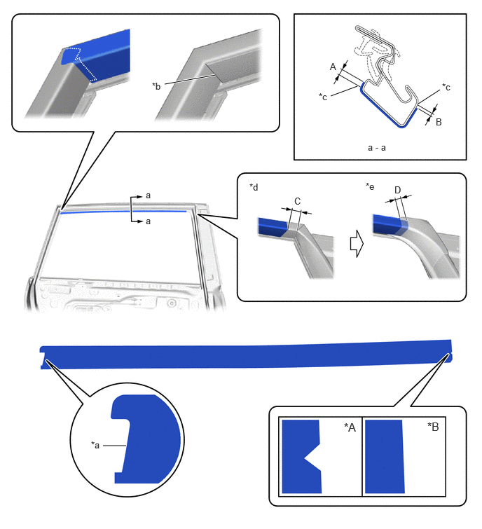
| *A | for RH Side | *B | for LH Side |
| *a | Point A | *b | Point B |
| *c | Edge of Curved Surface | *d | When removing Rear Door Frame Garnish LH |
| *e | When installing Rear Door Frame Garnish LH | - | - |
- Standard Measurement:
Area Measurement Area Measurement A 1.6 to 3.6 mm (0.0629 to 0.142 in.) B 1.0 mm (0.0393 in.) C 15 mm (0.590 in.) D 10 mm (0.393 in.)
Remove the release paper and install the upper inner black out tape LH.
- HINT:
-
Align the point (A) on the upper inner black out tape LH with the point (B) on the door frame and install the upper inner black out tape LH.
75952A
4.INSTALL FRONT INNER BLACK OUT TAPE LH
Refer to the illustration to position a new front inner black out tape LH.
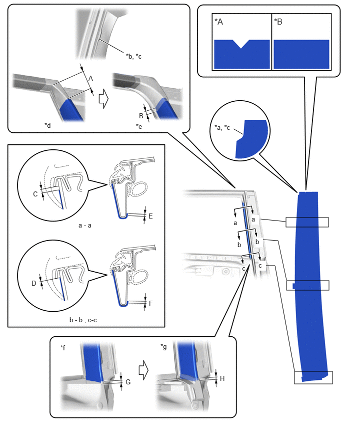
| *A | for RH Side | *B | for LH Side |
| *a | Point A | *b | Point B |
| *c | Edge of Curved Surface | *d | When removing Rear Door Frame Garnish LH |
| *e | When installing Rear Door Frame Garnish LH | *f | When removing Rear Door Weatherstrip LH |
| *g | When installing Rear Door Weatherstrip LH | - | - |
- Standard Measurement:
Area Measurement Area Measurement A 40 mm (1.57 in.) B 10 mm (0.393 in.) C 1.2 mm (0.0472 in.) D -1.0 to 1.0 mm (-0.0393 to 0.0393 in.) E 3.0 mm (0.118 in.) F 3.0 mm (0.118 in.) G 5.0 mm (0.196 in.) H 5.0 mm (0.196 in.)
Remove the release paper and install the front inner black out tape LH.
- HINT:
-
Align the point (A) on the front inner black out tape LH with the point (B) on the door frame and install the front inner black out tape LH.
67872
5.INSTALL REAR DOOR WEATHERSTRIP LH
68104
6.INSTALL REAR DOOR GLASS SUB-ASSEMBLY LH
68124C
7.INSTALL REAR DOOR QUARTER WINDOW GLASS LH
67408E
8.INSTALL REAR DOOR WINDOW DIVISION BAR SUB-ASSEMBLY LH
68152C
9.INSTALL REAR DOOR GLASS RUN LH
75740
10.INSTALL REAR DOOR BELT MOULDING ASSEMBLY LH
67674A
11.INSTALL REAR DOOR FRAME GARNISH LH
67842E
12.INSTALL REAR DOOR SERVICE HOLE COVER LH
68199
13.INSTALL REAR DOOR REAR BELT SEAL LH
68174A
14.INSTALL REAR DOOR INNER GLASS WEATHERSTRIP LH
67604
15.INSTALL REAR DOOR TRIM BOARD SUB-ASSEMBLY LH
16.INSTALL REAR POWER WINDOW REGULATOR SWITCH ASSEMBLY WITH REAR DOOR ARMREST BASE PANEL
74646
17.INSTALL DOOR ASSIST GRIP COVER LH
69278C
18.INSTALL REAR DOOR INSIDE HANDLE BEZEL LH
19.CONNECT CABLE TO NEGATIVE AUXILIARY BATTERY TERMINAL
20. INITIALIZATION AFTER RECONNECTING BATTERY TERMINAL
- HINT:
-
When disconnecting and reconnecting the battery, there is an automatic learning function that completes learning when the respective system is used.
21. INITIALIZE POWER WINDOW CONTROL SYSTEM
22. CHECK POWER WINDOW CONTROL SYSTEM
23. CHECK POWER DOOR LOCK CONTROL SYSTEM