EXTERIOR PANELS / TRIM BLACK OUT TAPE(for Front Door) INSTALLATION
CAUTION / NOTICE / HINT
- HINT:
- ·
Use the same procedure for the RH and LH sides.
·The procedure listed below is for the LH side.
PROCEDURE

 1. REPAIR INSTRUCTION
Clean the vehicle body surface.
Using a heat light, heat the vehicle body surface.
| Item | Temperature |
|---|---|
| Vehicle Body | 40 to 60°C (104 to 140°F) |
- CAUTION:
-
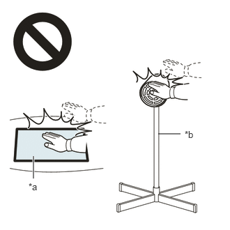 2.365,2 2.698,2 false 0.5,2.333 0.5,2.667 true 0.427,2.708 0.74,2.865 0.313,0.156 10 false *a 2.76,1.927 3.073,2.083 0.313,0.156 10 false *b
*a Heated Part *b Heat Light
- ·
Do not touch the heat light and heated parts.
·Touching the heat light may result in burns.
·Touching heated parts for a long time may result in burns.
- NOTICE:
-
Do not heat the vehicle body excessively.
Wipe off any tape adhesive residue with cleaner.
Installation temperature
When the ambient temperature is below 15°C (59°F), perform the installation procedure after warming the vehicle body surface (installation surface of the door frame) and tape up to between 20 and 30°C (68 and 86°F) using a heat light. When the ambient temperature is above 35°C (95°F), cool the vehicle body surface (installation surface of the door frame) and tape down to between 20 and 30°C (68 and 86°F) prior to installation.
- HINT:
- ·
The most appropriate temperature for installing the tape is 25°C (77°F).
·When the temperature is low, the tape becomes stiff and comes off easily. When the temperature is high, the tape elasticity increases.
Before installation
Remove any coating roughness or dirt on and around the vehicle body surface where the tape will be installed (installation surface of the door frame). If any roughness or dirt remains when pressing the tape onto the surface, air will be trapped under the tape and result in a poor appearance.
- HINT:
-
Spray water on the shop floor to settle any dust.
Key points for handling the tape
The tape bends and rolls up easily. Store the tape between flat pieces of cardboard or other similar objects and keep it dry and flat.
- NOTICE:
-
Do not bend the tape or leave it in high temperature places.
Key points for installation of the tape (How to use a squeegee and installation procedure for flat surfaces)
- NOTICE:
- ·
Position the tape accurately to achieve a neat finish and to avoid peeling.
·The tape cannot be reused because it deforms after removal.
To avoid air bubbles, slightly raise the part of the tape that is going to be applied so that its adhesive surface does not touch the vehicle body prematurely. Tilt the squeegee at 40 to 50° (pressing forward) or 30 to 45° (pulling) to the vehicle body surface and press the tape onto the vehicle body surface with a force of 20 to 30 N (2 to 3 kgf, 4.5 to 6.7 lbf) at a constant slow speed of 30 to 70 mm (1.18 to 2.76 in.) per second.
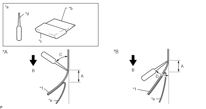
| *A | Pressing Forward | *B | Pulling |
| *1 | Black Out Tape | - | - |
| *a | Side View | *b | Non-padded Side |
| *c | Padded Side | *d | Squeegee |
| *e | Release Paper | - | - |
- Standard Measurement:
Area Measurement Area Measurement A 10 to 20 mm (0.394 to 0.787 in.) B 30 to 70 mm/sec. (1.18 to 2.76 in./sec.) C 40 to 50° (for pressing forward) D 30 to 45° (for pulling)
- NOTICE:
-
Be sure to observe the specified pressing speed, force and angle of the squeegee to avoid wrinkles or air bubbles.
- HINT:
- ·
Either angle of the squeegee (pressing forward or pulling) is acceptable.
·Be sure to apply the tape while removing the release paper 10 to 20 mm (0.394 to 0.787 in.) from the edge of the squeegee.
Key points for installation of the tape (How to use a squeegee and installation procedure for hemmed surfaces)
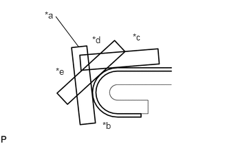
| *a | Squeegee |
| *b | Hem |
| *c | First |
| *d | Second |
| *e | Third |
If it is difficult to apply the tape, install it in several steps as shown in the illustration. Use your fingers or the padded surface of a squeegee to slowly apply the tape to the hem of the vehicle, especially for a small hem.
- HINT:
-
When applying tape to the backside of a hem, remove the release paper and use your fingers or the padded surface of a squeegee.
Key points for installation of the tape (How to use a squeegee and installation procedure for corners)
Remove the release paper and apply the tape carefully with your fingers.
Before applying the tape to each corner, heat the tape using a heat light and gradually apply it, avoiding wrinkles on the tape to achieve a neat finish.
Check after installation
After completing the installation, check if the tape is installed neatly. If the tape is not installed neatly, install a new tape.
- NOTICE:
-
Do not reuse the tape.
75922M
2.INSTALL NO. 1 BLACK OUT TAPE LH
Refer to the illustration to position a new No. 1 black out tape LH.
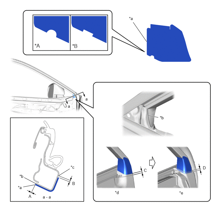
| *A | for RH Side | *B | for LH Side |
| *a | Point A | *b | Point B |
| *c | Edge of Curved Surface | *d | When removing Front Door Weatherstrip LH |
| *e | When installing Front Door Weatherstrip LH | - | - |
- Standard Measurement:
Area Measurement Area Measurement A -1.0 to 1.0mm (-0.0394 to 0.0394 in.) B 2.0 mm (0.0787 in.) C 4.0 mm (0.156 in.) D 4.4 mm (0.173 in.)
Remove the release paper and install the No. 1 black out tape LH.
- HINT:
-
Align the point (A) on the No. 1 black out tape LH with the point (B) on the door frame and install the No. 1 black out tape LH.
75939
3.INSTALL FRONT DOOR UPPER INNER BLACK OUT TAPE LH
Refer to the illustration to position a new front door upper inner black out tape LH.
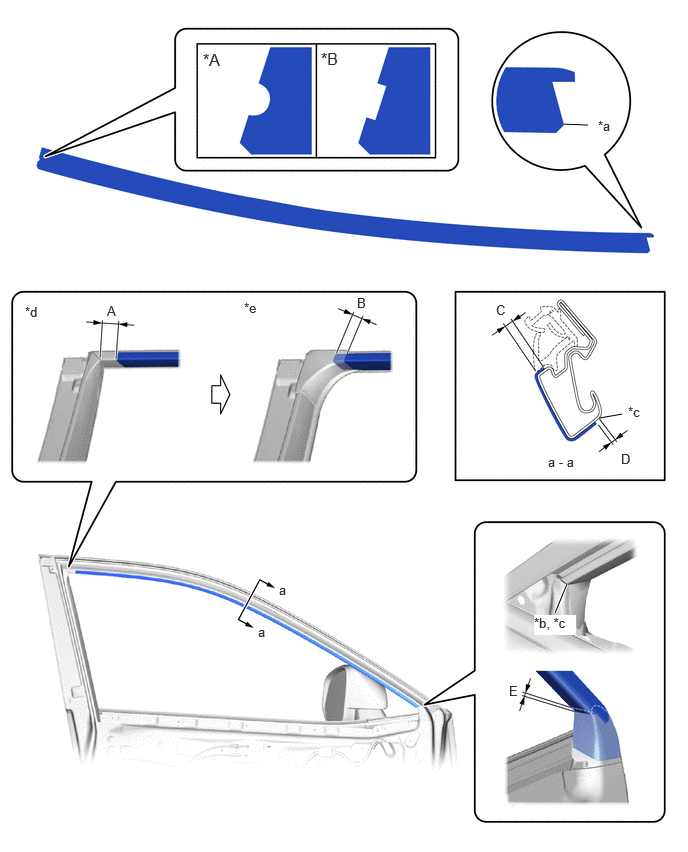
| *A | for RH Side | *B | for LH Side |
| *a | Point A | *b | Point B |
| *c | Edge of Curved Surface | *d | When removing Front Door Frame Garnish LH |
| *e | When installing Front Door Frame Garnish LH | - | - |
- Standard Measurement:
Area Measurement Area Measurement A 23 mm (0.905 in.) B 10 mm (0.394 in.) C 1.6 to 3.6 mm (0.0630 to 0.142 in.) D 1.0 mm (0.0394 in.) E 4.0 mm (0.156 in.) - -
Remove the release paper and install the front door upper inner black out tape LH.
- HINT:
-
Align the point (A) on the front door upper inner black out tape LH with the point (B) on the door frame and install the front door upper inner black out tape LH.
75969
4.INSTALL FRONT DOOR REAR INNER BLACK OUT TAPE LH
Refer to the illustration to position a new front door rear inner black out tape LH.
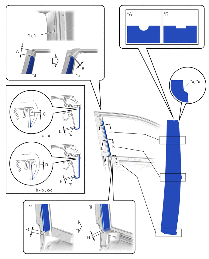
| *A | for RH Side | *B | for LH Side |
| *a | Point A | *b | Point B |
| *c | Edge of Curved Surface | *d | When removing Front Door Frame Garnish LH |
| *e | When installing Front Door Frame Garnish LH | *f | When removing Front Door Weatherstrip LH |
| *g | When installing Front Door Weatherstrip LH | - | - |
- Standard Measurement:
Area Measurement Area Measurement A 43 mm (1.69 in.) B 10 mm (0.394 in.) C 1.2 mm (0.0472 in.) D -1.0 to 1.0 mm (-0.0394 to 0.0394 in.) E 3.0 mm (0.118 in.) F 3.0 mm (0.118 in.) G 19 mm (0.748 in.) H 5.0 mm (0.197 in.)
Remove the release paper and install the front door rear inner black out tape LH.
- HINT:
-
Align the point (A) on the front door rear inner black out tape LH with the point (B) on the door frame and install the front door rear inner black out tape LH.
67862
5.INSTALL FRONT DOOR WEATHERSTRIP LH
68126
6.INSTALL FRONT DOOR FIX WINDOW GLASS LH
67402F
7.INSTALL FRONT DOOR FRONT LOWER FRAME SUB-ASSEMBLY LH
68151E
8.INSTALL FRONT DOOR GLASS RUN LH
67664C
9.INSTALL DOOR FRAME GARNISH LH
68102
10.INSTALL FRONT DOOR GLASS SUB-ASSEMBLY LH
75720
11.INSTALL FRONT DOOR BELT MOULDING ASSEMBLY LH
67832
12.INSTALL FRONT DOOR SERVICE HOLE COVER LH
68193C
13.INSTALL FRONT DOOR FRONT BELT SEAL LH
68172A
14.INSTALL FRONT DOOR INNER GLASS WEATHERSTRIP LH
67602
15.INSTALL FRONT DOOR TRIM BOARD SUB-ASSEMBLY LH
16.INSTALL MULTIPLEX NETWORK MASTER SWITCH ASSEMBLY WITH FRONT DOOR ARMREST BASE PANEL (for Driver Side)
17.INSTALL POWER WINDOW REGULATOR SWITCH ASSEMBLY WITH FRONT DOOR ARMREST BASE PANEL (for Front Passenger Side)
74640C
18.INSTALL DOOR ASSIST GRIP ASSEMBLY LH
69278B
19.INSTALL FRONT DOOR INSIDE HANDLE BEZEL LH
20.CONNECT CABLE TO NEGATIVE AUXILIARY BATTERY TERMINAL
21. INITIALIZATION AFTER RECONNECTING BATTERY TERMINAL
- HINT:
-
When disconnecting and reconnecting the battery, there is an automatic learning function that completes learning when the respective system is used.
22. INITIALIZE POWER WINDOW CONTROL SYSTEM
23. CHECK POWER WINDOW CONTROL SYSTEM
24. CHECK POWER DOOR LOCK CONTROL SYSTEM
25.INSPECT OUTER REAR VIEW MIRROR OPERATION