GF2A TRANSFER / 4WD / AWD DYNAMIC TORQUE VECTORING AWD SYSTEM AWD Control Switch Circuit
WIRING DIAGRAM
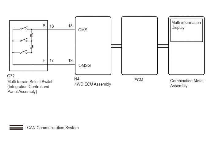
CAUTION / NOTICE / HINT
- NOTICE:
-
When the 4WD ECU assembly is replaced, before removing the 4WD ECU assembly, it is necessary to perform ECU Data Save to save the original 4WD ECU assembly information.
PROCEDURE
Turn the engine switch off.
Connect the GTS the DLC3.
Turn the engine switch on (IG).
Turn the GTS on.
Enter the following menus: Chassis / Four Wheel Drive / Dual Data List.
Simultaneously display the "Off-road Mode Selection Signal" four wheel drive Data List item and the "Off-road Guidance Status" engine Data List item.
According to the display on the GTS, read the Data List.
- Chassis > Four Wheel Drive > Data List
-
Tester Display Measurement Item Range Normal Condition Diagnostic Note Off-road Mode Selection Signal Off-road Mode Selection Signal Normal / Grass & Snow / Mud & Sand / Loose Rock / Mogul / Rock & Dirt / Rock / E-Lock - -
- Powertrain > Engine > Data List
-
Tester Display Measurement Item Range Normal Condition Diagnostic Note Off-road Guidance Status Off road mode status Normal, Grass & Snow, Mud & Sand, Loose Rock, Mogul or Rock & Dirt - -
Operate the multi-terrain select switch (integration control and panel assembly) and check that the Data List display and multi-information display message change according to switch operation.
- OK:
Multi-terrain Select Switch (Integration Control and Panel Assembly) Operation Data List Display Multi-information Display Message NORMAL Normal NORMAL MUD&SAND Mud & Sand MUD&SAND ROCK&DIRT Rock & Dirt ROCK&DIRT
- Result:
Result Proceed to When the switch is operated, the Data List display (Off-road Mode Selection Signal and Off-road Guidance Status ) and message do not change A When the switch is operated, the Data List display (Off-road Mode Selection Signal) changes, but the Data List display (Off-road Guidance Status ) and message do not change B When the switch is operated, the Data List display (Off-road Mode Selection Signal and Off-road Guidance Status) change, but the message does not change C When the switch is operated, the Data List display and message change normally D
A
B
M20C-FKS: Click hereEngine / Hybrid System>M20C-FKS (ENGINE CONTROL)>ECM>REMOVAL202405,999999,_51,_087036,_0418140,RM100000002JM0N,
M20D-FKS: Click hereEngine / Hybrid System>M20D-FKS (ENGINE CONTROL)>ECM>REMOVAL202304,202409,_51,_083058,_0401822,RM100000002A02S,202409,999999,_51,_083058,_0401822,RM100000002NRO9,
C
for SFTM Made: Click hereVehicle Interior>METER / GAUGE / DISPLAY>METER / GAUGE SYSTEM (for SFTM Made)>HOW TO PROCEED WITH TROUBLESHOOTING202405,999999,_58,_083097,_0694858,RM100000002LUR9,
for GTMC Made: Click hereVehicle Interior>METER / GAUGE / DISPLAY>METER / GAUGE SYSTEM (for GTMC Made)>HOW TO PROCEED WITH TROUBLESHOOTING202405,999999,_58,_083097,_0694857,RM100000002LUOC,
D
Inspect the multi-terrain select switch (integration control and panel assembly).
- Result:
Proceed to OK NG
OK
NG
Turn the engine switch off.
Disconnect the N4 4WD ECU assembly connector.
Disconnect the G32 multi-terrain select switch (integration control and panel assembly) connector.
Measure the resistance according to the value(s) in the table below.
- Standard Resistance:
Tester Connection Condition Specified Condition N4-18 (OMS) - G32-18 (B) Always Below 1 Ω N4-19 (OMSG) - G32-17 (E) Always Below 1 Ω N4-18 (OMS) or G32-18 (B) - Body ground Always 10 kΩ or higher N4-19 (OMSG) or G32-17 (E) - Body ground Always 10 kΩ or higher N4-18 (OMS) or G32-18 (B) - N4-19 (OMSG) or G32-17 (E) Always 10 kΩ or higher
- Result:
Proceed to OK NG
OK
NG