SEAT FRONT SEAT ASSEMBLY(for GTMC Made Power Seat) INSTALLATION
CAUTION / NOTICE / HINT
- CAUTION:
- ·
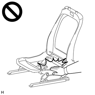
Wear protective gloves. Sharp areas on the parts may injure your hands.
·There is risk of injury.
- HINT:
- ·
Use the same procedure for the RH and LH sides.
·The following procedure is for the LH side.
PROCEDURE

 1.INSTALL FRONT SEAT ASSEMBLY LH
Place the front seat assembly LH in the vehicle as shown in the illustration.
- NOTICE:
- ·
2 or more people are required when carrying the front seat assembly LH into the vehicle.
·Protect the front seat legs.
·Be careful not to damage the front seat assembly LH, body exterior or interior parts.
Tilt the front seat assembly LH backward.
- NOTICE:
-
Do not damage the front seat assembly LH or interior parts.
Connect the connector of the front seat airbag assembly.
- HINT:
-
Refer to How to Connect or Disconnect Airbag Connector:
Connect each connector under the front seat assembly LH.
Attach each clamp and install the floor wire to the front seat assembly LH.
Insert the location pin of the front seat assembly LH on the seat rail front side into the hole on the vehicle side.
Temporarily install the front seat assembly LH with the 4 "TORX" screws.
Connect the cable to the negative (-) auxiliary battery terminal.
for Driver Side:
Operate the power seat switch knob LH (for slide and vertical) to move the seat cushion to the lowermost position.
Operate the slide and vertical power seat switch knob and move the front seat assembly LH to the rearmost position.
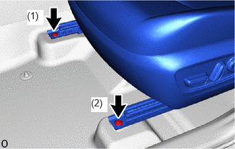
Using a T50 "TORX" socket wrench, tighten the 2 "TORX" screws in the order shown in the illustration.
- Torque:
- 37 N*m (377 kgf*cm, 27 ft.*lbf)
Operate the slide and vertical power seat switch knob and move the front seat assembly LH to the frontmost position.
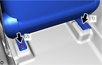
Using a T50 "TORX" socket wrench, tighten the 2 "TORX" screws in the order shown in the illustration.
- Torque:
- 37 N*m (377 kgf*cm, 27 ft.*lbf)
72138J
2.INSTALL FRONT SEAT REAR OUTER TRACK COVER LH
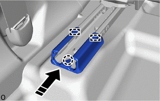

|
Install in this Direction |
Attach the guide and claw and install the front seat rear outer track cover LH as shown in the illustration.
72138H
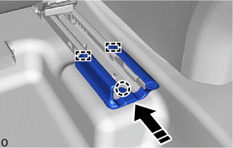
3.INSTALL FRONT SEAT TRACK REAR INNER COVER LH
|
|
Install in this Direction |
Attach the guide and claw and install the front seat track rear inner cover LH as shown in the illustration.
72124C
4.INSTALL FRONT OUTER SEAT TRACK BRACKET COVER LH
Operate the slide and vertical power seat switch knob and move the front seat assembly LH to the rearmost position.

|
|
Install in this Direction |
Attach the claw and guide and install the front outer seat track bracket cover LH as shown in the illustration.
72128A
5.INSTALL FRONT INNER SEAT TRACK BRACKET COVER LH
- HINT:
-
Use the same procedure described for the front outer seat track bracket cover LH.
71910A
6.INSTALL FRONT SEAT HEADREST ASSEMBLY
Install the front seat headrest assembly to the front seat assembly LH.
7. INITIALIZATION AFTER RECONNECTING AUXILIARY BATTERY TERMINAL
- HINT:
-
When disconnecting and reconnecting the auxiliary battery, there is an automatic learning function that completes learning when the respective system is used.
8. PERFORM DIAGNOSTIC SYSTEM CHECK
9.CHECK SRS WARNING LIGHT
10.INSPECT SEAT BELT WARNING SYSTEM
11.INSPECT FRONT POWER SEAT CONTROL SYSTEM
12.INSPECT SEAT HEATER SYSTEM (w/ Seat Heater System)
13.INSPECT CLIMATE CONTROL SEAT SYSTEM (w/ Climate Control Seat System)