K121 CVT CONTINUOUSLY VARIABLE TRANSAXLE SYSTEM P07457E Pressure Control Solenoid "A" Actuator Stuck On P08CC7E Shift Solenoid "J" Control Actuator Stuck On P09149E Gear Shift Position Circuit "A" Range/Performance Stuck On
DESCRIPTION
Using the current from the ECM, the shift solenoid valve SL1 controls the C1 clutch pressure and S1 synchronizer in accordance with the requested shift mode.
By controlling the current, the ECM controls the shift solenoid valve SC2 and switches the shift solenoid valve SL1 between the role of controlling the C1 clutch pressure and controlling the S1 synchronizer.
When the ECM requests the shift mode to be changed to gear mode, the S1 synchronizer is engaged and input torque is transferred to the 1st gear.
The shift stroke sensor detects the S1 synchronizer position using the magnet on the shift fork, and sends signals to the ECM.
| DTC No. | Detection Item | DTC Detection Condition | Trouble Area | MIL | DTC Output from | Priority | Note |
|---|---|---|---|---|---|---|---|
| P07457E | Pressure Control Solenoid "A" Actuator Stuck On | Any of the following conditions are met (2-trip detection logic):
·
When the ECM commands the S1 synchronizer to be released, the shift stroke sensor output value is 9.205 mm (0.362 in.) or more for 3 seconds or more. ·
When the ECM commands the S1 synchronizer to be released, the shift stroke sensor output value is 1.498 mm (0.0590 in.) or more for 8 seconds or more. |
·
Shift stroke sensor ·
Transmission valve body assembly (shift solenoid valve SL1 or SC2) ·
Continuously variable transaxle assembly |
Comes on | Engine | B | SAE Code:
P0747 |
| P08CC7E | Shift Solenoid "J" Control Actuator Stuck On | Any of the following conditions are met (2-trip detection logic):
·
When the ECM commands the S1 synchronizer to be released, the shift stroke sensor output value is 9.205 mm (0.362 in.) or more for 3 seconds or more. ·
When the ECM commands the S1 synchronizer to be released, the shift stroke sensor output value is 1.498 mm (0.0590 in.) or more for 8 seconds or more. |
·
Shift stroke sensor ·
Transmission valve body assembly (shift solenoid valve SL1 or SC2) ·
Continuously variable transaxle assembly |
Comes on | Engine | B | SAE Code:
P08CE |
| P09149E | Gear Shift Position Circuit "A" Range/Performance Stuck On | Any of the following conditions are met (2-trip detection logic):
·
When the ECM commands the S1 synchronizer to be released, the shift stroke sensor output value is 9.205 mm (0.362 in.) or more for 3 seconds or more. ·
When the ECM commands the S1 synchronizer to be released, the shift stroke sensor output value is 1.498 mm (0.0590 in.) or more for 8 seconds or more. |
·
Shift stroke sensor ·
Transmission valve body assembly (shift solenoid valve SL1 or SC2) ·
Continuously variable transaxle assembly |
Comes on | Engine | B | SAE Code:
P0915 |
MONITOR DESCRIPTION
When the shift solenoid valve SC2 turns ON, the shift solenoid valve SL1 controls the S1 synchronizer and moves it to the requested position according to the requested shift mode.
When the ECM detects that the S1 synchronizer is not in the appropriate position, it determines that the shift solenoid valve SL1, SC2 or shift stroke sensor is malfunctioning, illuminates the MIL and stores a DTC.
CONFIRMATION DRIVING PATTERN
- CAUTION:
-
When performing the confirmation driving pattern, obey all speed limits and traffic laws.
- HINT:
- ·
After repairs have been completed, clear the DTCs and then check that the vehicle has returned to normal by performing the following All Readiness check procedure.
·When clearing the permanent DTCs, refer to the Clear Permanent DTC procedure.
Clear the DTCs (even if no DTCs are stored, perform the clear DTC procedure).
Turn the ignition switch off and wait for 2 minutes or more.
Perform the D Position Shift Test inspection in Road Test. [*1]
- HINT:
-
[*1]: Normal judgment procedure.
-
The normal judgment procedure is used to complete DTC judgment and also used when clearing permanent DTCs.
Stop the vehicle.
Enter the following menus: Powertrain / Engine / Utility / All Readiness.
Input the DTC: P07457E, P08CC7E or P09149E.
Check the DTC judgment result.
| GTS Display | Description |
|---|---|
| NORMAL | ·
DTC judgment completed ·
System normal |
| ABNORMAL | ·
DTC judgment completed ·
System abnormal |
| INCOMPLETE | ·
DTC judgment not completed ·
Perform driving pattern after confirming DTC enabling conditions |
| N/A | ·
Unable to perform DTC judgment ·
Number of DTCs which do not fulfill DTC preconditions has reached ECU memory limit |
- HINT:
- ·
If the judgment result shows NORMAL, the system is normal.
·If the judgment result shows ABNORMAL, the system has a malfunction.
·If the judgment result shows INCOMPLETE or N/A, perform the normal judgment procedure again.
CAUTION / NOTICE / HINT
- NOTICE:
- ·
Perform the universal trip to clear permanent DTCs.
·Perform registration and/or initialization when parts related to the continuously variable transaxle system are replaced.
·Check that no DTCs are stored after performing initialization.
- HINT:
-
If any DTCs other than P07457E, P08CC7E or P09149E are output, perform troubleshooting for those DTCs first.
PROCEDURE
Read the DTCs using the GTS.
- Powertrain > Engine > Trouble Codes
- 50001 372
- Result:
Result Proceed to Only DTCs in the following table are output A DTCs other than the DTCs in the table below are output B
| Relevant DTC | |
|---|---|
| P07457E | Pressure Control Solenoid "A" Actuator Stuck On |
| P08CC7E | Shift Solenoid "J" Control Actuator Stuck On |
| P09149E | Gear Shift Position Circuit "A" Range/Performance Stuck On |
A
B
- Result:
Proceed to OK NG
OK
NG
Pre-procedure1
Disconnect the transmission wire connector from the shift solenoid valves SL1 and SC2.
Procedure1
Connect a positive (+) lead from the battery with a 21 W bulb to terminal 1 and a negative (-) lead to terminal 2 of the shift solenoid valve SL1 connector. Check that the valve moves and makes an operating sound.
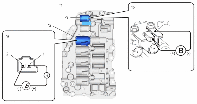
| *1 | Transmission Valve Body Assembly | *2 | Shift Solenoid Valve SL1 |
| *3 | Shift Solenoid Valve SC2 | - | - |
| *a | Component without harness connected
(Shift Solenoid Valve SL1) |
*b | Component without harness connected
(Shift Solenoid Valve SC2) |
- OK:
Valve moves and makes an operating sound.
Connect a positive (+) lead from the battery to the terminal of the shift solenoid valve SC2 connector and a negative (-) lead to the shift solenoid valve SC2 body. Check that the valve moves and makes an operating sound.
- OK:
Valve moves and makes an operating sound.
- Result:
Proceed to OK NG
Post-procedure1
None
OK
NG
- Result:
Proceed to NEXT
NEXT
for Registration: Click hereDrivetrain>K121 (CVT)>CONTINUOUSLY VARIABLE TRANSAXLE SYSTEM>REGISTRATION202304,999999,_52,_138176,_0584691,RM1000000029HF6,
for Initialization: Click hereDrivetrain>K121 (CVT)>CONTINUOUSLY VARIABLE TRANSAXLE SYSTEM>INITIALIZATION202304,202405,_52,_138176,_0584691,RM1000000029HF7,202405,202409,_52,_138176,_0584691,RM100000002JGMX,202409,999999,_52,_138176,_0584691,RM100000002NRHB,
- Result:
Proceed to NEXT
NEXT
for Registration: Click hereDrivetrain>K121 (CVT)>CONTINUOUSLY VARIABLE TRANSAXLE SYSTEM>REGISTRATION202304,999999,_52,_138176,_0584691,RM1000000029HF6,
for Initialization: Click hereDrivetrain>K121 (CVT)>CONTINUOUSLY VARIABLE TRANSAXLE SYSTEM>INITIALIZATION202304,202405,_52,_138176,_0584691,RM1000000029HF7,202405,202409,_52,_138176,_0584691,RM100000002JGMX,202409,999999,_52,_138176,_0584691,RM100000002NRHB,