RM36D0EC
_52
Drivetrain
_138176
K121 CVT
_0579403
SHIFT STROKE SENSOR
G
K121 CVT SHIFT STROKE SENSOR INSPECTION
PROCEDURE

 89419B
1.INSPECT SHIFT STROKE SENSOR
89419B
1.INSPECT SHIFT STROKE SENSOR
a.
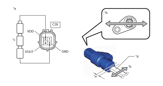
Connect 3 new dry-cell batteries (1.5 V each) in series.
b.
Prepare a magnet or equivalent tool.
c.
Connect a positive (+) lead from the batteries to terminal 2 (VDD) and a negative (-) lead to terminal 3 (GND).
2.229,0.979 2.646,1.229
0.417,0.25
5.083,3.083 5.667,2.5
5.667,2.5 5.917,2.5
true
2.25,1.927 2.667,2.26
true
1.51,2.271 1.927,1.938
true
1.521,1.375 1.938,1.708
true
0.573,0.292 0.885,0.448
0.313,0.156
10
false
*a
5.646,2.865 5.958,3.021
0.313,0.156
10
false
*b
0.552,1.677 0.865,1.833
0.313,0.156
10
false
*c
5.958,2.417 6.271,2.573
0.313,0.156
10
false
*d
4.125,3.302 4.323,3.479
0.198,0.177
10
false
*e
4.594,0.479 4.906,0.635
0.313,0.156
10
false
*b
1.198,1.302 1.656,1.5
0.458,0.198
10
false
VDD
1.094,2.208 1.552,2.406
0.458,0.198
10
false
VOUT
2.708,2.198 3.167,2.396
0.458,0.198
10
false
GND
2.302,1 2.76,1.198
0.458,0.198
10
false
C39
| *a | Component without harness connected
(Shift Stroke Sensor) |
*b | Magnet Movement Direction |
| *c | Dry Cell Battery | *d | Magnet |
| *e | 2.6 mm (0.102 in.) or less | - | - |
d.
Wave the magnet left and right 2.6 mm (0.102 in.) or less from the tip of the shift stroke sensor to output a high/low signal while measuring the voltage.
e.
Measure the voltage according to the value(s) in the table below.
- Standard Voltage (Combined Dry-cell Battery Voltage of 4.5 V):
Tester Connection Condition Specified Condition C39-4 (VOUT) - C39-3 (GND) High voltage 4.09 to 4.19 V Low voltage 0.36 to 0.45 V
- Reference Voltage (Combined Dry-cell Battery Voltage of 5.0 V):
Tester Connection Condition Specified Condition C39-4 (VOUT) - C39-3 (GND) High voltage 4.55 to 4.65 V Low voltage 0.4 to 0.5 V
If the result is not as specified, replace the shift stroke sensor.