SEAT FRONT SEAT ASSEMBLY(for GTMC Made Manual Seat) REASSEMBLY
CAUTION / NOTICE / HINT
- CAUTION:
-
- ·
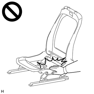
Wear protective gloves. Sharp areas on the parts may injure your hands.
·There is risk of injury.
- HINT:
- ·
Use the same procedure for the RH and LH sides.
·The following procedure is for the LH side.
PROCEDURE

 72125T
1.INSTALL FRONT SEAT REAR UPPER TRACK COVER LH
72125T
1.INSTALL FRONT SEAT REAR UPPER TRACK COVER LH

|
Install in this Direction |
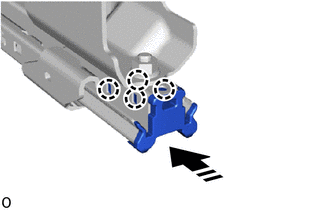
Attach the claw and install the front seat rear upper track cover LH as shown in the illustration.
72125S
2.INSTALL FRONT SEAT REAR UPPER TRACK COVER RH
- HINT:
-
Use the same procedure described for the LH side.
72266
3.INSTALL SEAT UPPER TRACK RAIL COVER LH
|
|
Install in this Direction |
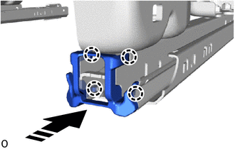
Attach the claw and install the seat upper track rail cover LH as shown in the illustration.
72265
4.INSTALL SEAT UPPER TRACK RAIL COVER RH
- HINT:
-
Use the same procedure described for the LH side.
72211C
5.INSTALL SEAT TRACK ADJUSTING HANDLE
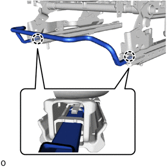
Attach the claw and install the seat track adjusting handle.
71052A
6.INSTALL FRONT SEAT CUSHION SPRING SUB-ASSEMBLY LH
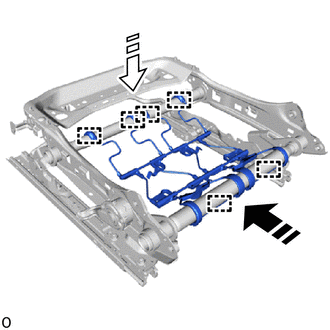
| *a | Hook A |
| *b | Hook B |
|
|
Install in this Direction (1) |

|
Install in this Direction (2) |
Push in the installation direction (1) shown in the illustration to attach the hook A.
Push in the installation direction (2) shown in the illustration, attach the hook B to install the front seat cushion spring sub-assembly LH.
7181B
7.INSTALL FRONT SEAT CUSHION WIRE HARNESS HOLDER LH
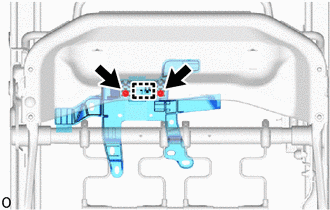
Attach the guide.
Install the front seat cushion wire harness holder LH with the 2 screws.
71874A
8.INSTALL FRONT SEAT LOWER CUSHION SHIELD LH (for Driver Side)
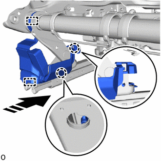
| *a | Hook |
| *b | Guide |
|
|
Install in this Direction |
Attach the guide and claw as shown in the illustration.
Attach the hook and install the front seat lower cushion shield LH.
71873A
9.INSTALL FRONT SEAT LOWER CUSHION SHIELD RH (for Driver Side)
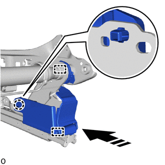
| *a | Hook |
| *b | Guide |
|
|
Install in this Direction |
Attach the guide and claw as shown in the illustration.
Attach the hook and install the front seat lower cushion shield RH.
71876G
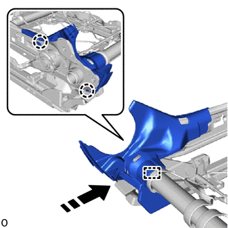
10.INSTALL LH SEAT RECLINING ADJUSTER INSIDE COVER LH (for Driver Side)
|
|
Install in this Direction |
Attach the hook and claw and install the LH seat reclining adjuster inside cover LH as shown in the illustration.
71876F
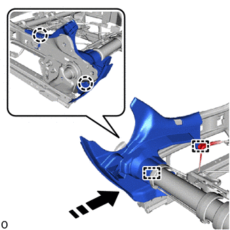
11.INSTALL RH SEAT RECLINING ADJUSTER INSIDE COVER LH (for Front Passenger Side)
| *a | Hook |
| *b | Clamp |
|
|
Install in this Direction |
Attach the hook and claw and install the RH seat reclining adjuster inside cover LH as shown in the illustration.
71875G
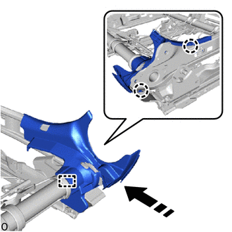
12.INSTALL LH SEAT RECLINING ADJUSTER INSIDE COVER RH (for Driver Side)
|
|
Install in this Direction |
Attach the hook and claw and install the LH seat reclining adjuster inside cover RH as shown in the illustration.
71875F
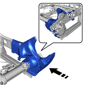
13.INSTALL RH SEAT RECLINING ADJUSTER INSIDE COVER RH (for Front Passenger Side)
|
|
Install in this Direction |
Attach the hook and claw and install the RH seat reclining adjuster inside cover RH as shown in the illustration.
82666M
14.INSTALL CONNECTOR HOLDER (for Front Passenger Side)
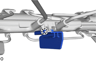
Attach the claw and install the connector holder.
71072S
15.INSTALL SEPARATE TYPE FRONT SEAT CUSHION COVER
- HINT:
-
When installing a separate type front seat cushion cover, refer to Precaution in order to prevent wrinkles from forming.
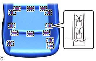
Attach the hook and install the separate type front seat cushion cover.
- NOTICE:
-
Be careful not to dirty or damage the separate type front seat cushion cover.
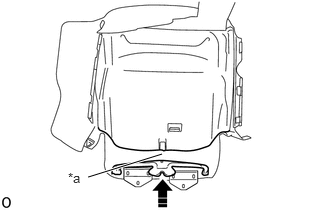
| *a | Band |
|
|
Install in this Direction |
Attach the band.
16.INSTALL SEPARATE TYPE FRONT SEAT CUSHION COVER WITH PAD
Attach the hook and install the separate type front seat cushion cover with pad.
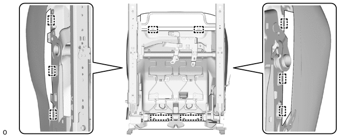
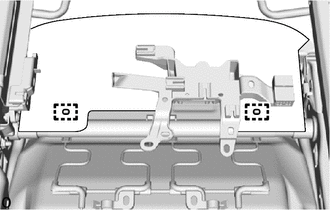
Attach the hook.
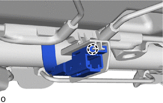
for Front Passenger Side:
Attach the claw.
71759D
17.INSTALL FRONT NO. 2 SEATBACK HOOK
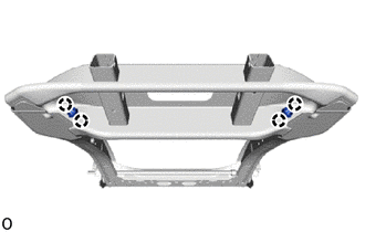
Attach the claw and install 2 new front No. 2 seatback hooks.
- NOTICE:
-
Check that the claw of the front No. 2 seatback hook are securely attached.
71587B
18.INSTALL FRONT SEATBACK EDGE PROTECTOR
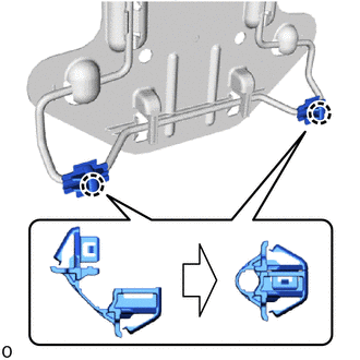
Attach the claw and install the 2 front seatback edge protectors.
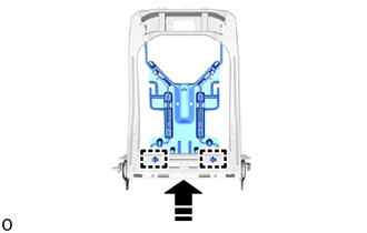
|
|
Install in this Direction |
Attach the clamp.
73920A
19.INSTALL FRONT SEAT AIR BAG ASSEMBLY LH
71074S
20.INSTALL SEPARATE TYPE FRONT SEATBACK COVER
- HINT:
-
When installing a separate type front seatback cover, refer to Precaution in order to prevent wrinkles from forming.
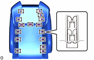
Attach the hook and install the separate type front seatback cover to the separate type front seatback pad.
- NOTICE:
-
Be careful not to dirty or damage the separate type front seatback cover.
21.INSTALL SEPARATE TYPE FRONT SEATBACK COVER WITH PAD
Set the separate type front seatback cover with pad.
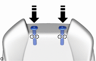
|
|
Install in this Direction |
Attach the claw and install the 2 front seat headrest supports as shown in the illustration.
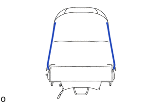
Close the 2 fasteners.
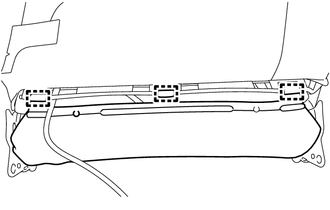
| *a | Outshoot |
Attach the hook.
- NOTICE:
- ·
Be careful not to overlap on the route of the wire harness.
·Pass the wire harness through the outside of the outshoot.
22.INSTALL SEPARATE TYPE FRONT SEATBACK ASSEMBLY
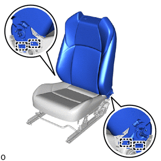
Attach the guide.
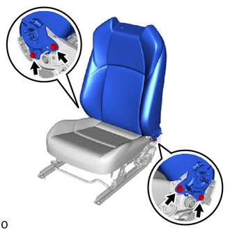
Temporarily install the separate type front seatback assembly with the 4 bolts.
Tighten the 4 bolts.
- Torque:
- 42 N*m (428 kgf*cm, 31 ft.*lbf)
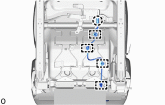
Attach the claw and clamp.
- NOTICE:
-
Attach the claw first.
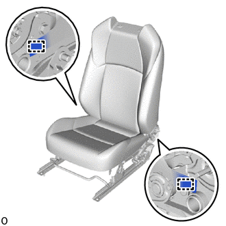
Attach the hook.
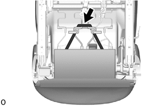
Attach the band.
72498A
23.INSTALL VERTICAL ADJUSTER BRACKET COVER LH (for Driver Side)
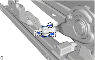
Attach the guide and claw and install the vertical adjuster bracket cover LH.
71862
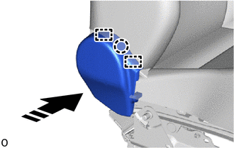
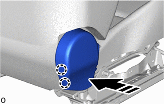
24.INSTALL FRONT SEAT INNER CUSHION SHIELD LH (for Driver Side)
|
|
Install in this Direction |
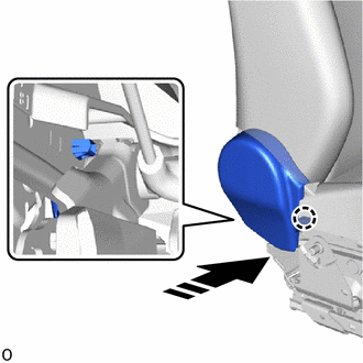
Attach the claw as shown in the illustration.
|
|
Install in this Direction |
Attach the claw and guide as shown in the illustration.
|
|
Install in this Direction |
Attach the claw and install the front seat inner cushion shield LH as shown in the illustration.
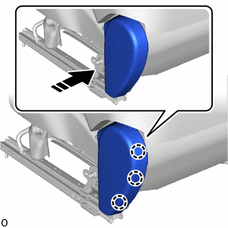
71861
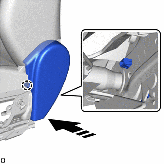
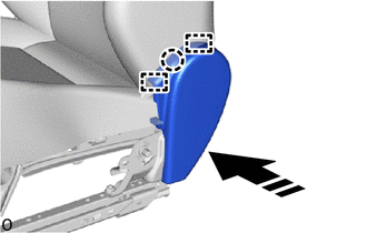
25.INSTALL FRONT SEAT INNER CUSHION SHIELD RH (for Front Passenger Side)
|
|
Install in this Direction |
Attach the claw as shown in the illustration.
|
|
Install in this Direction |
Attach the claw and guide as shown in the illustration.
|
|
Install in this Direction |
Attach the claw and install the front seat inner cushion shield RH as shown in the illustration.
71812D
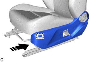
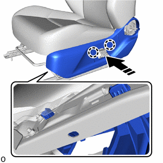
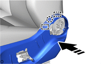
26.INSTALL FRONT SEAT CUSHION SHIELD LH (for Driver Side)
|
|
Install in this Direction |
Attach the guide as shown in the illustration.
|
|
Install in this Direction |
Attach the claw as shown in the illustration.
|
|
Install in this Direction |
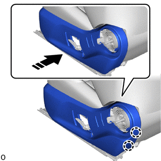
Attach the claw and guide as shown in the illustration.
|
|
Install in this Direction |
Attach the claw and install the front seat cushion shield LH as shown in the illustration.
71811D
27.INSTALL FRONT SEAT CUSHION SHIELD RH (for Front Passenger Side)
|
|
Install in this Direction |
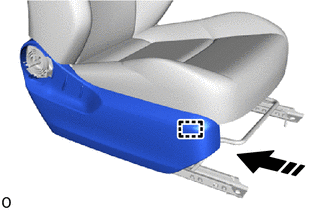
Attach the guide as shown in the illustration.
|
|
Install in this Direction |
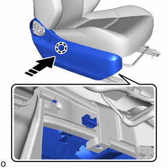
Attach the claw as shown in the illustration.
|
|
Install in this Direction |
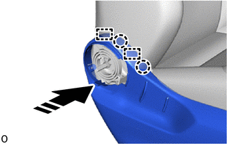
Attach the claw and guide as shown in the illustration.
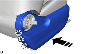
|
|
Install in this Direction |
Attach the claw and install the front seat cushion shield RH as shown in the illustration.
71849
28.INSTALL SEAT ADJUSTER COVER CAP LH (for Driver Side)
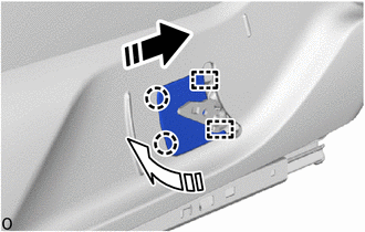
|
|
Install in this Direction (1) |
|
|
Install in this Direction (2) |
Push in the installation direction (1) shown in the illustration to attach the guide.
Push in the installation direction (2) shown in the illustration and attach the claw and install the seat adjuster cover cap LH.
72526E
29.INSTALL RECLINING ADJUSTER RELEASE HANDLE LH
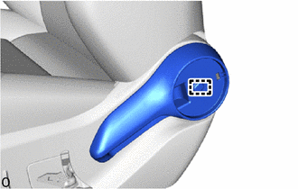
Attach the guide and install the reclining adjuster release handle LH.
72552B
30.INSTALL RECLINING HINGE COVER LH
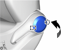
|
|
Install in this Direction |
Attach the guide and claw and install the reclining hinge cover LH as shown in the illustration.
72495
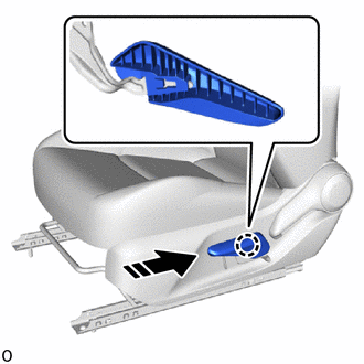
31.INSTALL VERTICAL ADJUSTING HANDLE LH (for Driver Side)
|
|
Install in this Direction |
Attach the claw and install the vertical adjusting handle LH as shown in the illustration.
73240
32.INSTALL FRONT SEAT INNER BELT ASSEMBLY LH (for Driver Side)
73230
33.INSTALL FRONT SEAT INNER BELT ASSEMBLY RH (for Front Passenger Side)