SEAT FRONT SEAT ASSEMBLY(for SFTM Made Manual Seat) PRECAUTION
- HINT:
- ·
The following procedures are used to prevent wrinkles from forming when installing the seat cover. Make sure to follow the procedures correctly.
- ·
The shape of the seat shown in the illustration may differ from the actual seat.
SEAT COVER SET
Align the center cutout of the pad with the V-point of the cover.
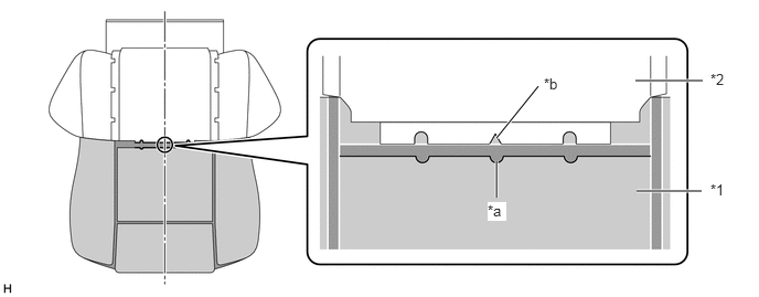
| *1 | Pad | *2 | Cover |
| *a | Center Cutout of Pad | *b | Cover V-point |
INSTALL WIRE
Install the wire to the cover as shown in the illustration.
- HINT:
-
Make sure the wire is in the center of the cover.
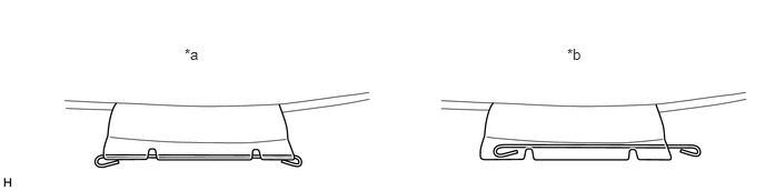 1.729,0.427 2.042,0.583 0.313,0.156 10 false *a 5.313,0.427 5.625,0.583 0.313,0.156 10 false *b
*a Correct *b Incorrect
INSTALL HOG RING
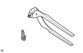
Using hog ring pliers, bend the hog rings into the shape shown in the illustration.
- HINT:
-
Make sure to bend the hog rings into the proper shape. Wrinkles will form if improperly shaped hog rings are used.
Install the hog rings in the order of the wires shown in the illustration.
- HINT:
-
 0.573,1.573 0.885,1.729 0.313,0.156 10 false *a 2.573,0.448 2.885,0.604 0.313,0.156 10 false *b 1.552,1.125 1.865,1.281 0.313,0.156 10 false (1) 1.844,1.813 2.156,1.969 0.313,0.156 10 false (2) 1.51,2.365 1.823,2.521 0.313,0.156 10 false (3) 2.354,1.76 2.667,1.917 0.313,0.156 10 false (5) 1.031,1.146 1.344,1.302 0.313,0.156 10 false (4) 2,0.771 2.313,0.927 0.313,0.156 10 false (6)
*a Vehicle Exterior *b Vehicle Interior
- ·
Install in the following order: Center of seatback, side closest to vehicle exterior, and then side closest to vehicle interior.
- ·
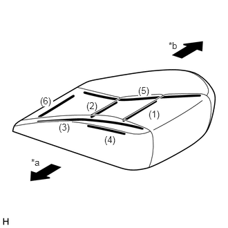 0.469,2.365 0.781,2.521 0.313,0.156 10 false *a 2.542,0.604 2.854,0.76 0.313,0.156 10 false *b 2.24,1.635 2.552,1.792 0.313,0.156 10 false (1) 1.302,1.51 1.615,1.667 0.313,0.156 10 false (2) 0.885,1.833 1.083,1.99 0.198,0.156 10 true (3) 1.573,2.021 1.885,2.188 0.313,0.167 10 false (4) 2.083,1.281 2.281,1.448 0.198,0.167 10 true (5) 0.604,1.438 0.802,1.604 0.198,0.167 10 true (6)
*a Vehicle Exterior *b Vehicle Interior
Install in the following order: Center of seat cushion, side closest to vehicle exterior, and then side closest to vehicle interior.
- ·
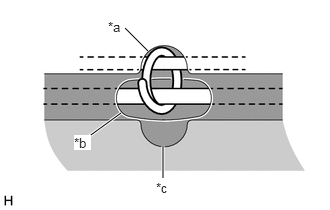 1.302,0.292 1.542,0.531 false 0.917,1.427 1.26,1.177 true 1.698,1.854 1.698,1.521 true 1.125,0.198 1.438,0.354 0.313,0.156 10 false *a 0.771,1.406 0.948,1.563 0.177,0.156 10 true *b 1.625,1.875 1.938,2.031 0.313,0.156 10 false *c
*a Cover Hole *b Pad Groove *c Pad Cutout
Install the hog ring so that it is centered in the cutout of the pad.
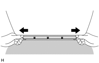
After installing the hog rings, hold the seam allowance on both ends of the cover and pull to match the pad and cover installation areas.
- HINT:
-
If the cover is not matched to the pad, wrinkles will form.
Push the cover seam allowance securely into the groove in the pad.
- HINT:
-
Make sure to completely push the seam allowance into the groove. Wrinkles will form if any of the seam allowance is outside the groove.
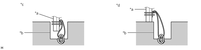 1.396,0.5 1.906,0.677 false 4.802,0.333 5.198,0.333 true 4.552,1.167 5.469,1.167 true 0.865,1.167 1.781,1.167 true 1.24,0.385 1.552,0.542 0.313,0.156 10 false *a 0.698,1.094 1.01,1.25 0.313,0.156 10 false *b 0.729,0.073 1.042,0.229 0.313,0.156 10 false *c 4.146,0.104 4.458,0.26 0.313,0.156 10 false *d 4.625,0.25 4.938,0.406 0.313,0.156 10 false *a 4.375,1.094 4.688,1.25 0.313,0.156 10 false *b
*a Cover Seam Allowance *b Pad Groove *c Correct *d Incorrect
INSTALL WEBBING (w/ Airbag)

| *a | Cover Webbing |
| *b | Pad Hole |
Pass the webbing through the pad hole, and then stretch the webbing so there are no wrinkles.
- NOTICE:
-
If there are wrinkles in the webbing, wrinkles will appear on the surface of the cover.
CHECK COVER POSITION
Fold the cover back as shown in the illustration and check that the cover V-points and the pad mark-off lines are approximately aligned.
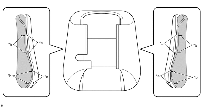
| *a | Cover V-point | *b | Pad Mark-off Line |
INSTALL COVER
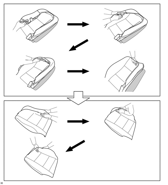
Align the cover of the seatback with the center of the seatback pad and the cover of the seat cushion with the center of the seat cushion pad. Afterward, install the covers starting from the vehicle exterior and working toward the vehicle interior.
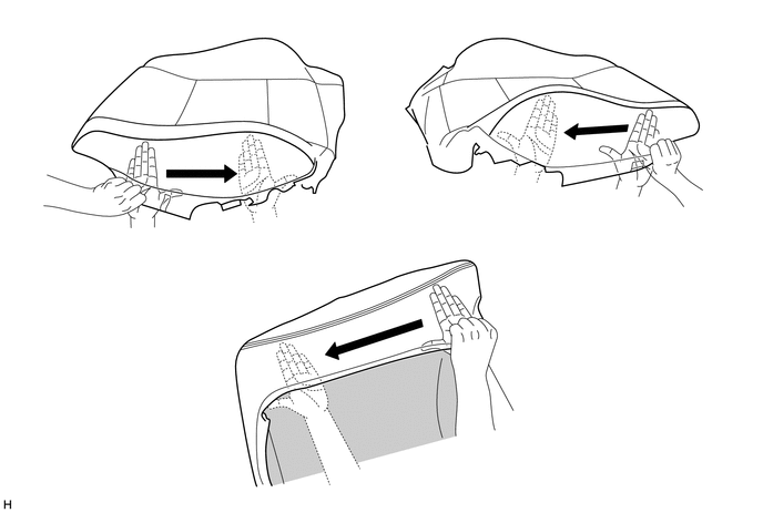
While removing wrinkles by hand as shown in the illustration, install the seatback cover by starting from the bottom and working toward the shoulders, and then install the seat cushion cover by starting from the front and working toward the rear.
- HINT:
- ·
Do not push the pad into the cover. Instead, secure the pad and install the cover to the pad.
- ·
For Seatback Side:
When installing the cover to the outer side, install the cover up until the installation area of the outer side headrest support.
- ·
Do not apply an excessive amount of force when covering the corners, as doing so may cause the cover to tear or fray.
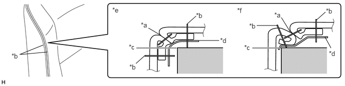
Align the cover seam line with the edges of the pad.
- HINT:
- ·
Double-stitch type:
 6.031,0.667 5.844,0.365 false 6.76,0.25 6.573,0.417 false 5.75,0.531 5.333,0.531 false 5.823,1 5.24,1 true 3.667,1 2.833,1 true 3.01,1.156 2.823,1.323 false 4.073,0.333 3.885,0.5 false 3.313,0.719 3.083,0.583 false 6.75,0.771 6.875,1 false 4.552,0.844 4.135,0.844 false 0.896,0.938 0.406,1.135 false 0.979,1.083 0.427,1.135 false 2.927,0.438 3.24,0.594 0.313,0.156 10 false *a 5.073,0.906 5.385,1.063 0.313,0.156 10 false *c 6.833,1.031 7.063,1.281 0.229,0.25 10 false *d 2.333,0.125 2.646,0.281 0.313,0.156 10 false *e 4.927,0.135 5.24,0.292 0.313,0.156 10 false *f 5.698,0.229 6.01,0.385 0.313,0.156 10 false *a 5.177,0.458 5.49,0.615 0.313,0.156 10 false *b 2.677,0.896 2.99,1.052 0.313,0.156 10 false *c 6.771,0.146 7.083,0.302 0.313,0.156 10 false *b 2.688,1.313 3,1.469 0.313,0.156 10 false *b 4.073,0.24 4.385,0.396 0.313,0.156 10 false *b 4.573,0.76 4.802,1.01 0.229,0.25 10 false *d 0.24,1.083 0.552,1.24 0.313,0.156 10 false *b
*a Cover Seam Line *b Cover Seam (Stitch) *c Pad Edge *d Felt *e Correct *f Incorrect
- ·
Single-stitch type:
Align the seam allowance in a single direction.
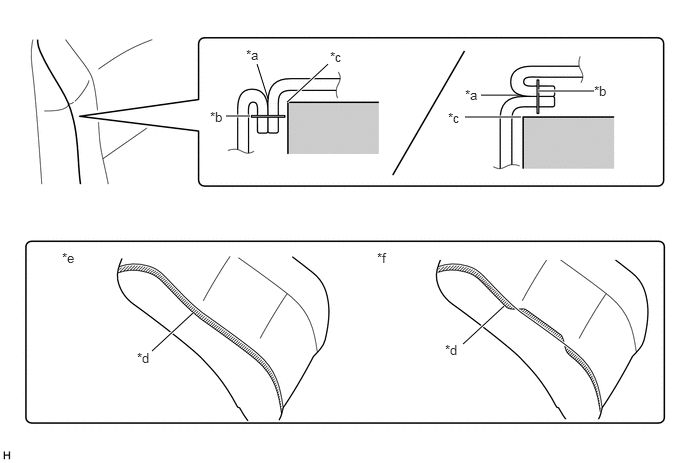 2.792,1.031 2.677,0.667 false 5.427,0.99 5.01,0.99 false 5.427,1.219 4.844,1.219 true 6.188,0.948 5.604,0.948 true 3.417,0.667 2.99,1.063 true 2.604,1.208 2.354,1.208 true 2.01,3.26 1.583,3.656 true 5.25,3.188 4.823,3.583 true 6.188,0.865 6.5,1.021 0.313,0.156 10 false *b 4.667,1.146 4.979,1.302 0.313,0.156 10 false *c 1.427,3.646 1.74,3.802 0.313,0.156 10 false *d 0.646,2.604 0.958,2.76 0.313,0.156 10 false *e 3.927,2.604 4.24,2.76 0.313,0.156 10 false *f 2.563,0.49 2.875,0.646 0.313,0.156 10 false *a 4.844,0.906 5.156,1.063 0.313,0.156 10 false *a 3.438,0.51 3.75,0.667 0.313,0.156 10 false *c 2.188,1.135 2.5,1.292 0.313,0.156 10 false *b 4.635,3.563 4.948,3.719 0.313,0.156 10 false *d
*a Cover Seam Line *b Cover Seam (Stitch) *c Pad Edge *d Seam Allowance of Cover *e Correct *f Incorrect
Push the cover seam allowance securely into the groove in the pad.
- HINT:
-
Make sure to completely push the seam allowance into the groove. Wrinkles will form if any of the seam allowance is outside the groove.
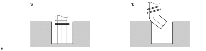 1.021,0.063 1.333,0.219 0.313,0.156 10 false *a 4.542,0.063 4.854,0.219 0.313,0.156 10 false *b
*a Correct *b Incorrect
REMOVE WRINKLES
After installing the cover with pad to the seat frame, use your fingers to trace the seam line of each part and remove wrinkles.
- NOTICE:
-
If there are wrinkles in the webbing, wrinkles will appear on the surface of the cover.
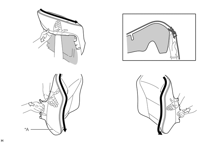 1.031,4.365 1.781,4.365 true 0.823,4.281 1.135,4.438 0.313,0.156 10 false *A
*A w/ Airbag - -
CHECKS TO PERFORM AFTER WORK IS FINISHED
Smooth the cover as shown in the illustration and make sure that there are no wrinkles.
- HINT:
- ·
If wrinkles remain, it is very likely that the hog rings were not properly bent or covering was not properly performed.
- ·
If the cover appears to be off to one side, it is very likely that the hog ring positions are incorrect.
- ·
If waves form in the seam line, it is very likely that the seam allowance is not in the groove or the position of the felt is incorrect.
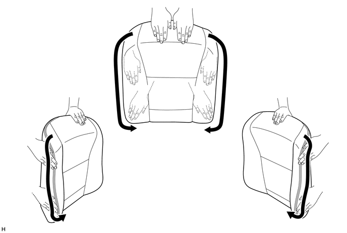
SEAT COVER WIRE PREPARATION METHOD
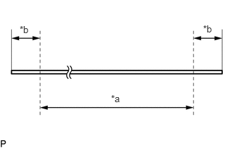
| *a | Dimension of Seat Cover Wire after Preparation |
| *b | Length Necessary for Bending |
Cut the seat cover wire to a length which includes the amount necessary for bending the ends (approximately 20 mm (0.787 in.) on one side, approximately 40 mm (1.57 in.) for both sides).
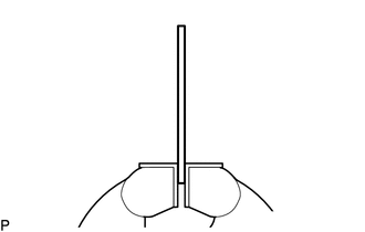
Secure approximately 10 mm (0.393 in.) of the end of the seat cover wire in a vise.
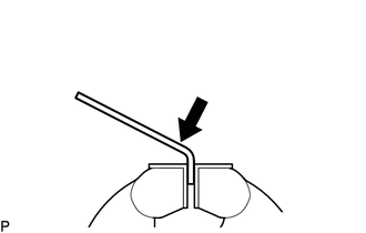
Bend the seat cover wire near the vise by hand.
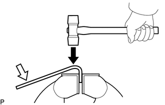
Using a hammer, lightly tap the wire until it forms an angle of 90° or less.
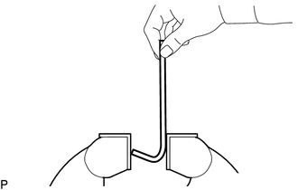
Remove the wire from the vise, and then secure the wire in the vise lengthwise.
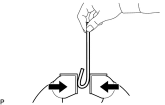
While securing the wire by hand to prevent the wire from rotating, tighten the vise.