REAR SUSPENSION REAR SUSPENSION MEMBER(for 2WD) INSTALLATION
PROCEDURE

 1.INSTALL HOLE PLUG
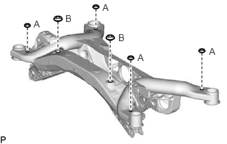
Install the 6 hole plugs to the rear suspension member sub-assembly.
- HINT:
-
There are 2 different shapes of hole plug.
52271E
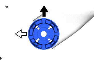
2.INSTALL REAR SUSPENSION MEMBER FRONT BODY MOUNTING CUSHION (for LH Side)
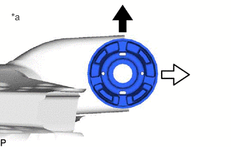
| *a | View from Underneath |

|
Front of the Vehicle |

|
Outside of the Vehicle |
Confirm the installation direction and temporarily install a new rear suspension member front body mounting cushion.
- NOTICE:
- ·
Position the rear suspension member front body mounting cushion in the correct direction.
·Do not apply lubricant to the outer sleeve of the rear suspension member front body mounting cushion.

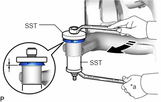
Install SST as shown in the illustration.
- SST
- 09570-24011
09830-10010 (09830-01010, 09830-01020, 09830-01040, 09830-01050)
- NOTICE:
-
Apply molybdenum grease to the threads and tip of the SST center bolt before use.

| *a | Hold |

|
Turn |
Using SST, install the rear suspension member front body mounting cushion until there is no clearance between the rear suspension member sub-assembly and rear suspension member front body mounting cushion.
- SST
- 09570-24011
09830-10010 (09830-01010, 09830-01020, 09830-01040, 09830-01050)
- NOTICE:
-
If the rear suspension member sub-assembly is scratched, apply paint to the scratched areas of the rear suspension member sub-assembly.
Remove SST from the rear suspension member sub-assembly.
52271E
3.INSTALL REAR SUSPENSION MEMBER FRONT BODY MOUNTING CUSHION (for RH Side)
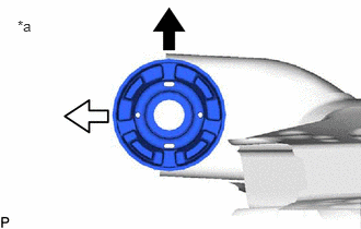
| *a | View from Underneath |
|
|
Front of the Vehicle |
|
|
Outside of the Vehicle |
Confirm the installation direction and temporarily install a new rear suspension member front body mounting cushion.
- NOTICE:
- ·
Position the rear suspension member front body mounting cushion in the correct direction.
·Do not apply lubricant to the outer sleeve of the rear suspension member front body mounting cushion.
Install SST using the same procedure as for the rear suspension member front body mounting cushion (for LH Side).
- SST
- 09570-24011
09830-10010 (09830-01010, 09830-01020, 09830-01040, 09830-01050)
- NOTICE:
-
Apply molybdenum grease to the threads and tip of the SST center bolt before use.
Using SST, install the rear suspension member front body mounting cushion until there is no clearance between the rear suspension member sub-assembly and rear suspension member front body mounting cushion.
- SST
- 09570-24011
09830-10010 (09830-01010, 09830-01020, 09830-01040, 09830-01050)
- NOTICE:
-
If the rear suspension member sub-assembly is scratched, apply paint to the scratched areas of the rear suspension member sub-assembly.
- HINT:
-
Perform the same procedure as for the rear suspension member front body mounting cushion (for LH Side).
Remove SST from the rear suspension member sub-assembly.
52275A
4.INSTALL REAR SUSPENSION MEMBER REAR BODY MOUNT CUSHION LH

| *a | View from Underneath |
|
|
Front of the Vehicle |
|
|
Outside of the Vehicle |
Confirm the installation direction and temporarily install a new rear suspension member rear body mount cushion LH.
- NOTICE:
- ·
Position the rear suspension member rear body mount cushion LH in the correct direction.
·Do not apply lubricant to the outer sleeve of the rear suspension member rear body mount cushion LH.
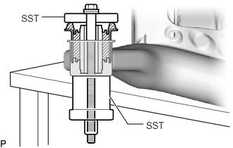
Install SST as shown in the illustration.
- SST
- 09710-28031 (09711-02030, 09711-02040, 94622-51200)
09950-60021 (09951-00720, 09951-00890)
- NOTICE:
-
Apply molybdenum grease to the threads and tip of the SST center bolt before use.
| *a | Hold |
|
|
Turn |
Using SST, install the rear suspension member rear body mount cushion LH until there is no clearance between the rear suspension member sub-assembly and rear suspension member rear body mount cushion LH.
- SST
- 09710-28031 (09711-02030, 09711-02040, 94622-51200)
09950-60021 (09951-00720, 09951-00890)
- NOTICE:
-
If the rear suspension member sub-assembly is scratched, apply paint to the scratched areas of the rear suspension member sub-assembly.
Remove SST from the rear suspension member sub-assembly.
52275A
5.INSTALL REAR SUSPENSION MEMBER REAR BODY MOUNT CUSHION RH
| *a | View from Underneath |
|
|
Front of the Vehicle |
|
|
Outside of the Vehicle |
Confirm the installation direction and temporarily install a new rear suspension member rear body mount cushion RH.
- NOTICE:
- ·
Position the rear suspension member rear body mount cushion RH in the correct direction.
·Do not apply lubricant to the outer sleeve of the rear suspension member rear body mount cushion RH.
Install SST using the same procedure as for the rear suspension member rear body mount cushion LH.
- SST
- 09710-28031 (09711-02030, 09711-02040, 94622-51200)
09950-60021 (09951-00720, 09951-00890)
- NOTICE:
-
Apply molybdenum grease to the threads and tip of the SST center bolt before use.
Using SST, install the rear suspension member rear body mount cushion RH until there is no clearance between the rear suspension member sub-assembly and rear suspension member rear body mount cushion RH.
- SST
- 09710-28031 (09711-02030, 09711-02040, 94622-51200)
09950-60021 (09951-00720, 09951-00890)
- NOTICE:
-
If the rear suspension member sub-assembly is scratched, apply paint to the scratched areas of the rear suspension member sub-assembly.
- HINT:
-
Perform the same procedure as for the rear suspension member rear body mount cushion LH.
Remove SST from the rear suspension member sub-assembly.
48790
6.INSTALL REAR UPPER CONTROL ARM ASSEMBLY LH
48770A
7.INSTALL REAR UPPER CONTROL ARM ASSEMBLY RH
- HINT:
-
Perform the same procedure as for the LH side.
51206A
8.INSTALL REAR SUSPENSION MEMBER SUB-ASSEMBLY
Install the 4 rear suspension member cushions to the rear suspension member sub-assembly.
- HINT:
-
When reusing the rear suspension member cushion, make sure to check its identification mark and install it to the correct position.
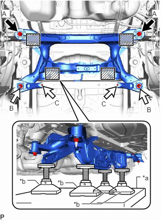
| *a | Engine Lifter |
| *b | Attachment |

|
Attachment and Wooden Block Placement Location |
Using an engine lifter and 4 attachments or equivalent tools, support the rear suspension member sub-assembly as shown in the illustration.
- CAUTION:
-
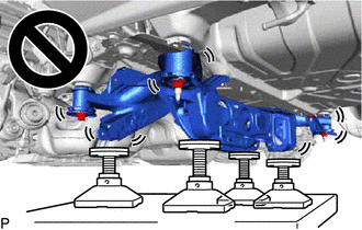
- ·
The rear suspension member sub-assembly is a very heavy component. Make sure that it is supported securely.
·If the rear suspension member sub-assembly is not securely supported, it may drop, resulting in serious injury.
- NOTICE:
- ·
Use attachments or equivalent tools to keep the rear suspension member sub-assembly level.
·Keep supporting the rear suspension member sub-assembly until the installation has been completed.
Raise the rear suspension member sub-assembly until there is no clearance between the rear suspension member sub-assembly and vehicle.
Install the rear suspension member sub-assembly with the 2 rear suspension member lower stoppers, rear suspension member lower brace LH and rear suspension member lower brace RH, 2 bolts and 4 nuts.
- Torque:
- Bolt A : 158 N*m (1611 kgf*cm, 117 ft.*lbf)
- Nut B : 158 N*m (1611 kgf*cm, 117 ft.*lbf)
- Nut C : 18 N*m (184 kgf*cm, 13 ft.*lbf)
48790
9.TEMPORARILY INSTALL REAR UPPER CONTROL ARM ASSEMBLY LH
Temporarily install the rear upper control arm assembly LH to the rear axle carrier sub-assembly LH with the bolt and nut.
- NOTICE:
- ·
Insert the bolt with the threaded end facing the rear of the vehicle.
·Because the nut has its own stopper, do not turn the nut. Tighten the bolt with the nut secured.
48770A
10.TEMPORARILY INSTALL REAR UPPER CONTROL ARM ASSEMBLY RH
- HINT:
-
Perform the same procedure as for the LH side.
48720A
11.TEMPORARILY INSTALL REAR NO. 1 SUSPENSION ARM ASSEMBLY LH
48710A
12.TEMPORARILY INSTALL REAR NO. 1 SUSPENSION ARM ASSEMBLY RH
- HINT:
-
Perform the same procedure as for the LH side.
48740F
13.TEMPORARILY INSTALL REAR NO. 2 SUSPENSION ARM ASSEMBLY LH
48730F
14.TEMPORARILY INSTALL REAR NO. 2 SUSPENSION ARM ASSEMBLY RH
- HINT:
-
Perform the same procedure as for the LH side.
48258C
15.INSTALL REAR LOWER COIL SPRING INSULATOR LH
48258B
16.INSTALL REAR LOWER COIL SPRING INSULATOR RH
- HINT:
-
Perform the same procedure as for the LH side.
48231B
17.INSTALL REAR COIL SPRING LH
48231A
18.INSTALL REAR COIL SPRING RH
- HINT:
-
Perform the same procedure as for the LH side.
48812
19.INSTALL REAR STABILIZER BAR
47319F
20.CONNECT REAR FLEXIBLE HOSE LH
Connect the rear flexible hose LH to the rear flexible hose bracket with the bolt.
- Torque:
- 29 N*m (296 kgf*cm, 21 ft.*lbf)
47318F
21.CONNECT REAR FLEXIBLE HOSE RH
- HINT:
-
Perform the same procedure as for the LH side.
22.STABILIZE SUSPENSION
48840A
23.INSTALL REAR STABILIZER LINK ASSEMBLY LH
48830D
24.INSTALL REAR STABILIZER LINK ASSEMBLY RH
- HINT:
-
Perform the same procedure as for the LH side.
48720A
25.INSTALL REAR NO. 1 SUSPENSION ARM ASSEMBLY LH
48710A
26.INSTALL REAR NO. 1 SUSPENSION ARM ASSEMBLY RH
- HINT:
-
Perform the same procedure as for the LH side.
48740F
27.INSTALL REAR NO. 2 SUSPENSION ARM ASSEMBLY LH
Install the rear No. 2 suspension arm assembly LH (rear axle carrier sub-assembly side) with the bolt.
48730F
28.INSTALL REAR NO. 2 SUSPENSION ARM ASSEMBLY RH
- HINT:
-
Perform the same procedure as for the LH side.
48790
29.INSTALL REAR UPPER CONTROL ARM ASSEMBLY LH
Install the rear upper control arm assembly LH to the rear axle carrier sub-assembly LH with the bolt.
- Torque:
- 73 N*m (744 kgf*cm, 54 ft.*lbf)
- NOTICE:
-
Because the nut has its own stopper, do not turn the nut. Tighten the bolt with the nut secured.
48770A
30.INSTALL REAR UPPER CONTROL ARM ASSEMBLY RH
- HINT:
-
Perform the same procedure as for the LH side.
58399D
31.INSTALL NO. 2 FLOOR UNDER COVER (for Gasoline Model)
58398F
32.INSTALL NO. 1 FLOOR UNDER COVER (for Gasoline Model)
58166A
33.INSTALL FRONT FLOOR COVER LH (for Gasoline Model)
58166A
34.INSTALL FRONT FLOOR COVER RH (for Gasoline Model)
51420
35.INSTALL NO. 2 ENGINE UNDER COVER ASSEMBLY (for Gasoline Model)
51441
36.INSTALL NO. 1 ENGINE UNDER COVER (for Gasoline Model)
53896B
37.INSTALL FRONT FENDER FRONT SPLASH SHIELD LH (for Gasoline Model)
53895B
38.INSTALL FRONT FENDER FRONT SPLASH SHIELD RH (for Gasoline Model)
58327B
39.INSTALL MAIN MUFFLER HEAT INSULATOR
17430
40.INSTALL TAIL EXHAUST PIPE ASSEMBLY
41.INSTALL REAR WHEEL
48740F
42.INSTALL REAR NO. 2 SUSPENSION ARM ASSEMBLY LH
Install the rear No. 2 suspension arm assembly LH (rear suspension member sub-assembly side) with the nut.
48730F
43.INSTALL REAR NO. 2 SUSPENSION ARM ASSEMBLY RH
- HINT:
-
Perform the same procedure as for the LH side.
44.INSPECT FOR EXHAUST GAS LEAK
45.INSPECT AND ADJUST REAR WHEEL ALIGNMENT
46. INITIALIZATION AFTER RECONNECTING AUXILIARY BATTERY TERMINAL (for HV Model)
- HINT:
-
When disconnecting and reconnecting the auxiliary battery, there is an automatic learning function that completes learning when the respective system is used.