M20D-FKS INTAKE / EXHAUST EXHAUST PIPE INSTALLATION
PROCEDURE

 17577
1.INSTALL NO. 7 EXHAUST PIPE SUPPORT BRACKET
17577
1.INSTALL NO. 7 EXHAUST PIPE SUPPORT BRACKET
Install the No. 7 exhaust pipe support bracket to the body with the 2 bolts.
- Torque:
- 29 N*m (296 kgf*cm, 21 ft.*lbf)
Install the exhaust pipe support to the No. 7 exhaust pipe support bracket.
17576A
2.INSTALL NO. 6 EXHAUST PIPE SUPPORT BRACKET
Install the No. 6 exhaust pipe support bracket to the body with the 2 bolts.
- Torque:
- 29 N*m (296 kgf*cm, 21 ft.*lbf)
Install the exhaust pipe support to the No. 6 exhaust pipe support bracket.
17572B
3.INSTALL NO. 2 EXHAUST PIPE SUPPORT BRACKET
17408
4.INSTALL TAIL EXHAUST PIPE BAFFLE SUB-ASSEMBLY
- HINT:
- ·
Perform this procedure only when replacement of the tail exhaust pipe baffle sub-assembly is necessary.
·If the tail exhaust pipe baffle sub-assembly is removed, replace it with a new one.
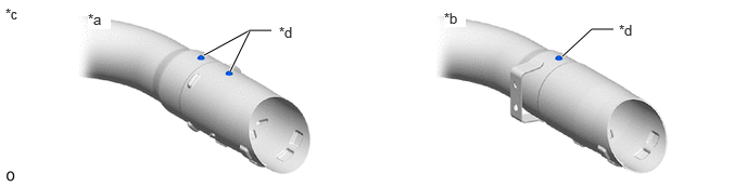
·There are 2 types of shapes for the tail exhaust pipe assembly.
 5.885,0.281 5.677,0.281 5.677,0.281 5.396,0.542 true 2.604,0.292 2.396,0.292 2.396,0.292 1.958,0.531 true 2.208,0.688 2.396,0.302 true 4.26,0.094 4.469,0.26 0.208,0.167 10 true *b 0.844,0.104 1.063,0.281 0.219,0.177 10 true *a 0.052,0.052 0.271,0.229 0.219,0.177 10 true *c 5.938,0.208 6.156,0.385 0.219,0.177 10 true *d 2.677,0.229 2.896,0.406 0.219,0.177 10 true *d
*a 2 protrusion type *b 1 protrusion type *c tail exhaust pipe end *d Protrusion
2 protrusion type:
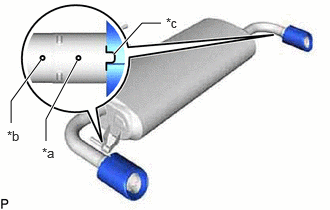
| *a | Protrusion (for position alignment) |
| *b | Protrusion (for stopper) |
| *c | Cutout |
Align the cutout of a new tail exhaust pipe baffle sub-assembly with the protrusion (for position alignment) of the tail exhaust pipe assembly as shown in the illustration.
Insert the exhaust tailpipe baffle sub-assembly to the position where it can be pressed in by hand.
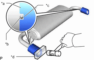
| *a | Baffle Edge |
| *b | Protrusion (for stopper) |
| *c | Cutout |
| *d | Wooden Block |
Using a plastic-faced hammer and wooden block, uniformly tap the tail exhaust pipe baffle sub-assembly onto the tail exhaust pipe assembly.
- NOTICE:
- ·
Lightly tap the top and bottom of the exhaust tailpipe baffle sub-assembly so that the exhaust tailpipe baffle sub-assembly is pressed in without a tilt.
·Press the exhaust tailpipe baffle sub-assembly in until the protrusion (for stopper) on the exhaust tailpipe assembly is fit into the cutout area of the exhaust tailpipe baffle sub-assembly.
·Check that there is no looseness in the exhaust tailpipe baffle sub-assembly.
1 protrusion type:
Set a new tail exhaust pipe baffle sub-assembly to the tail exhaust pipe assembly.
Insert the exhaust tailpipe baffle sub-assembly to the position where it can be pressed in by hand.
| *a | Baffle Edge |
| *b | Protrusion |
| *c | Cutout |
| *d | Wooden Block |
Using a plastic-faced hammer and wooden block, uniformly tap the tail exhaust pipe baffle sub-assembly onto the tail exhaust pipe assembly.
- NOTICE:
- ·
Lightly tap the top and bottom of the exhaust tailpipe baffle sub-assembly so that the exhaust tailpipe baffle sub-assembly is pressed in without a tilt.
·Press the exhaust tailpipe baffle sub-assembly in until the protrusion on the exhaust tailpipe assembly is fit into the cutout area of the exhaust tailpipe baffle sub-assembly.
·Check that there is no looseness in the exhaust tailpipe baffle sub-assembly.
17410
5.INSTALL FRONT EXHAUST PIPE ASSEMBLY
Install a new gasket to the front exhaust pipe assembly.
Connect the front exhaust pipe assembly to the 2 exhaust pipe supports.
Install the front exhaust pipe assembly to the exhaust manifold with 2 new nuts.
- Torque:
- 43 N*m (438 kgf*cm, 32 ft.*lbf)
89425A
6.INSTALL NO. 2 EXHAUST GAS TEMPERATURE SENSOR
89425
7.INSTALL EXHAUST GAS TEMPERATURE SENSOR
89467C
8.INSTALL AIR FUEL RATIO SENSOR (for Sensor 2)
17430
9.INSTALL TAIL EXHAUST PIPE ASSEMBLY
Install a new gasket to the front exhaust pipe assembly.
Connect the tail exhaust pipe assembly to the 3 exhaust pipe supports.
Install the tail exhaust pipe assembly to the front exhaust pipe assembly with 2 new bolts.
- Torque:
- 43 N*m (438 kgf*cm, 32 ft.*lbf)
10.INSPECT FOR EXHAUST GAS LEAK
If gas is leaking, tighten the areas necessary to stop the leak. Replace damaged parts as necessary.
Perform "Inspection After Repair" after repairing an exhaust gas leak.