RM36D0EC
_56
Audio / Visual / Telematics
_083086
AUDIO / VIDEO
_0593011
AUDIO AND VISUAL SYSTEM
C
AUDIO / VIDEO AUDIO AND VISUAL SYSTEM B153587 Image Processing Module "B" Video Signal Missing Message
DESCRIPTION
This DTC is stored when a video signal line is disconnected.
| DTC No. | Detection Item | DTC Detection Condition | Trouble Area | DTC Output from | Priority |
|---|---|---|---|---|---|
| B153587 | NTSC (from Park Assist/Monitoring ECU) Missing Message | Parking assist ECU video signal error
(2 trip detection logic) |
·
Panoramic view monitor system ·
Harness or connector ·
Radio and display receiver assembly |
Navigation System | B |
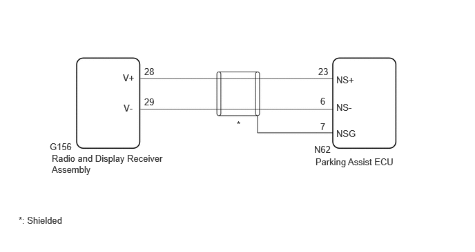
WIRING DIAGRAM
5.073,1.125 5.531,1.323
0.458,0.198
10
false
NS+
5.073,1.542 5.531,1.74
0.458,0.198
10
false
NS-
5.073,1.938 5.531,2.135
0.458,0.198
10
false
NSG
1.854,1.094 2.313,1.292
0.458,0.198
10
false
V+
1.865,1.552 2.323,1.75
0.458,0.198
10
false
V-
0.781,2.313 2.49,2.677
1.708,0.365
10
false
Radio and Display Receiver Assembly
4.76,2.365 6.281,2.771
1.521,0.406
10
false
Parking Assist ECU
2.177,1 3.031,1.292
0.854,0.292
10
false
28
2.177,1.458 3.188,1.75
1.01,0.292
10
false
29
0.281,3.25 1.531,3.531
1.25,0.281
10
false
*: Shielded
3.573,1.802 4.031,2
0.458,0.198
10
false
*
4.833,1.448 5.292,1.646
0.458,0.198
10
false
6
4.802,1 5.26,1.198
0.458,0.198
10
false
23
4.833,1.833 5.292,2.031
0.458,0.198
10
false
7
0.75,2.135 1.156,2.344
0.406,0.208
10
false
G156
4.74,2.177 5.198,2.375
0.458,0.198
10
false
N62
CAUTION / NOTICE / HINT
- NOTICE:
-
Depending on the parts that are replaced during vehicle inspection or maintenance, performing initialization, registration or calibration may be needed.
PROCEDURE
1.CHECK PANORAMIC VIEW MONITOR SYSTEM
a.
Check if the panoramic view monitor system is malfunctioning.
- Result:
Result Proceed to Malfunction does not occur A Malfunction occurs B
A
2.CHECK HARNESS AND CONNECTOR (PARKING ASSIST ECU - RADIO AND DISPLAY RECEIVER ASSEMBLY)
B
2.CHECK HARNESS AND CONNECTOR (PARKING ASSIST ECU - RADIO AND DISPLAY RECEIVER ASSEMBLY)
a.
Disconnect the N62 parking assist ECU connector.
b.
Disconnect the G156 radio and display receiver assembly connector.
c.
Measure the resistance according to the value(s) in the table below.
- Standard Resistance:
Tester Connection Condition Specified Condition N62-23 (NS+) - G156-28 (V+) Always Below 1 Ω N62-6 (NS-) - G156-29 (V-) Always Below 1 Ω N62-23 (NS+) - Body ground Always 10 kΩ or higher N62-6 (NS-) - Body ground Always 10 kΩ or higher
- Result:
Proceed to OK NG
OK
REPLACE RADIO AND DISPLAY RECEIVER ASSEMBLY
NG
REPAIR OR REPLACE HARNESS OR CONNECTOR