FRONT SUSPENSION FRONT LOWER SUSPENSION ARM INSTALLATION
CAUTION / NOTICE / HINT
- HINT:
- ·
Use the same procedure for the RH side and LH side.
·The following procedure is for the LH side.
PROCEDURE

 48069
1.INSTALL FRONT LOWER NO. 1 SUSPENSION ARM SUB-ASSEMBLY
48069
1.INSTALL FRONT LOWER NO. 1 SUSPENSION ARM SUB-ASSEMBLY
Install the front lower arm bushing stopper to the front lower No. 1 suspension arm sub-assembly.
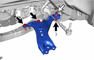
Install the front lower No. 1 suspension arm sub-assembly to the front engine support member sub-assembly with the 3 bolts and nut in the order shown in the illustration.
- Torque:
- Bolt (1), (2) : 200 N*m (2039 kgf*cm, 148 ft.*lbf)
- Bolt (3) : 135 N*m (1377 kgf*cm, 100 ft.*lbf)
- NOTICE:
-
Because the nut has its own stopper, do not turn the nut. Tighten the bolt with the nut secured.
Connect the front lower No. 1 suspension arm sub-assembly to the front lower ball joint assembly with the bolt and 2 nuts.
- Torque:
- 92 N*m (938 kgf*cm, 68 ft.*lbf)
53737D
2.INSTALL FRONT FENDER APRON SEAL LH (for LH Side)
53736E
3.INSTALL FRONT FENDER APRON SEAL RH (for RH Side)
58166A
4.INSTALL FRONT FLOOR COVER LH (for LH Side)
58166A
5.INSTALL FRONT FLOOR COVER RH (for RH Side)
6.INSTALL ENGINE UNDER COVER HEAT INSULATOR (for A25B-FXS)
7.INSTALL ENGINE UNDER COVER HEAT INSULATOR (for A25D-FXS)
8.INSTALL ENGINE UNDER COVER HEAT INSULATOR (for A25F-FXS)
51420
9.INSTALL NO. 2 ENGINE UNDER COVER ASSEMBLY
51441
10.INSTALL NO. 1 ENGINE UNDER COVER
53896B
11.INSTALL FRONT FENDER FRONT SPLASH SHIELD LH
53895B
12.INSTALL FRONT FENDER FRONT SPLASH SHIELD RH
13.INSTALL FRONT WHEEL
14.INSPECT AND ADJUST FRONT WHEEL ALIGNMENT