M20D-FKS COOLING COOLING FAN SYSTEM Cooling Fan Circuit
DESCRIPTION
The ECM calculates an appropriate cooling fan speed based on the engine coolant temperature, air conditioning switch status, refrigerant pressure, engine speed and vehicle speed, and sends a signal to the cooling fan ECU (fan with motor assembly). The cooling fan ECU (fan with motor assembly) steplessly control the speed of the cooling fan based on the duty cycle signal sent from the ECM. By sending signals to the cooling fan ECU (fan with motor assembly) in accordance with the driving conditions and by controlling the cooling fan speed optimally with the ECM, both high cooling performance and quietness are ensured.
WIRING DIAGRAM
CAUTION / NOTICE / HINT
- NOTICE:
- ·
Inspect the fuses for circuits related to this system before performing the following procedure.
·Make sure to perform the necessary procedures (adjustment, calibration, initialization, or registration) after parts related to the cooling fan system have been removed/installed or replaced.
PROCEDURE
Connect the GTS to the DLC3.
Turn the ignition switch to ON.
Turn the GTS on.
Enter the following menus: Powertrain / Engine / Active Test / Control the Engine Cooling Fan Duty Ratio.
- Powertrain > Engine > Active Test
-
Tester Display Control the Engine Cooling Fan Duty Ratio - 50004 372 11
Check the operation of the cooling fan while operating it using the GTS.
- OK:
GTS Operation Fan Operation 30 - 100% Cooling fan operates 0% Cooling fan stops
- Result:
Result Proceed to OK A Cooling fan does not operate B Cooling fan does not stop C
A
B
C
Disconnect the A25 fan with motor assembly connector.
Disconnect the A116 ECM connector.
Measure the resistance according to the value(s) in the table below.
- Standard Resistance:
Tester Connection Condition Specified Condition A25-3 (SI) or A116-65 (RFC) - Body ground Always 10 kΩ or higher
- Result:
Proceed to OK NG
OK
NG
Disconnect the A25 fan with motor assembly connector.
Connect the GTS to the DLC3.
Turn the ignition switch to ON.
Turn the GTS on.
Enter the following menus: Powertrain / Engine / Active Test / Control the Engine Cooling Fan Duty Ratio.
- Powertrain > Engine > Active Test
-
Tester Display Control the Engine Cooling Fan Duty Ratio - 50004 372 11
Operate the cooling fan motor (fan with motor assembly) using the Active Test function and measure the resistance according to the value(s) in the table below.
- Standard Resistance:
Tester Connection GTS Operation Specified Condition A25-3 (SI) - Body ground Before Active Test (0%) → During Active Test (30% - 75%) Before Active Test (0%): Resistance is stable → During Active Test (30% - 75%): Resistance fluctuates*
- HINT:
-
*: Using the Active Test, duty control of the transistors in the ECM will be performed. Due to the duty control, resistance of the RFC terminal will be unstable during the Active Test. If the resistance is stable before the Active Test and fluctuates while performing the Active Test, it can be determined that the transistor is operating. If the transistor does not operate during the Active Test, the ECM may be malfunctioning.
- Result:
Proceed to OK NG
OK
NG
Disconnect the A25 fan with motor assembly connector.
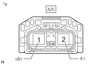
| *a | Front view of wire harness connector
(to Fan with Motor Assembly) |
Measure the voltage according to the value(s) in the table below.
- Standard Voltage:
Tester Connection Condition Specified Condition A25-1 (+B1) - A25-2 (E1) Always 11 to 14 V
- Result:
Proceed to OK NG
OK
NG
Disconnect the A25 fan with motor assembly connector.
Turn the ignition switch to ON.
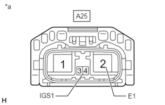
| *a | Front view of wire harness connector
(to Fan with Motor Assembly) |
Measure the voltage according to the value(s) in the table below.
- Standard Voltage:
Tester Connection Condition Specified Condition A25-4 (IGS1) - A25-2 (E1) Ignition switch ON 11 to 14 V
- Result:
Proceed to OK NG
OK
NG
Disconnect the A25 fan with motor assembly connector.
Remove the EFI-MAIN NO. 1 relay from the No. 1 engine room relay block and No. 1 junction block assembly.
Measure the resistance according to the value(s) in the table below.
- Standard Resistance:
Tester Connection Condition Specified Condition A25-4 (IGS1) - 5 (EFI-MAIN NO. 1 relay) Always Below 1 Ω
- Result:
Result OK NG
OK
NG
Disconnect the A25 fan with motor assembly connector.
Measure the resistance according to the value(s) in the table below.
- Standard Resistance:
Tester Connection Condition Specified Condition A25-2 (E1) - Body ground Always Below 1 Ω
- Result:
Proceed to OK NG
OK
NG
Disconnect the A25 fan with motor assembly connector.
Connect the GTS to the DLC3.
Turn the ignition switch to ON.
Turn the GTS on.
Enter the following menus: Powertrain / Engine / Active Test / Control the Engine Cooling Fan Duty Ratio.
- Powertrain > Engine > Active Test
-
Tester Display Control the Engine Cooling Fan Duty Ratio - 50004 372 11
Operate the cooling fan motor (fan with motor assembly) using the Active Test function and measure the resistance according to the value(s) in the table below.
- Standard Resistance:
Tester Connection GTS Operation Specified Condition A25-3 (SI) - Body ground Before Active Test (0%) → During Active Test (30% - 75%) Before Active Test (0%): Resistance is stable → During Active Test (30% - 75%): Resistance fluctuates*
- HINT:
-
*: Using the Active Test, duty control of the transistors in the ECM will be performed. Due to the duty control, resistance of the RFC terminal will be unstable during the Active Test. If the resistance is stable before the Active Test and fluctuates while performing the Active Test, it can be determined that the transistor is operating. If the transistor does not operate during the Active Test, the ECM may be malfunctioning.
- Result:
Proceed to OK NG
OK
NG
Disconnect the A25 fan with motor assembly connector.
Disconnect the A116 ECM connector.
Measure the resistance according to the value(s) in the table below.
- Standard Resistance:
Tester Connection Condition Specified Condition A25-3 (SI) - A116-65 (RFC) Always Below 1 Ω
- Result:
Result OK NG
OK
NG